Last time we looked at my electric relay solution to a problem presented by a 120 volt alternating current (VAC) drive motor operating within an x-ray film processing machine. Now let’s see what happens when we press the button to set the microprocessor into operation.
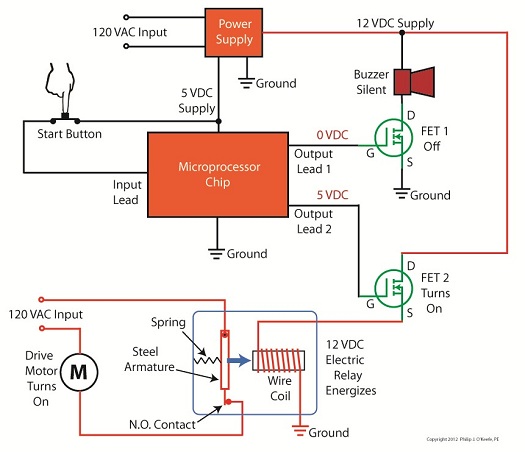
Figure 1Figure 1 shows that when the button is depressed, the computer program contained within the microprocessor chip goes into action, signaling the start of the control initiative. 5 volts direct current (VDC) is supplied to Output Lead 2, and FET 2 (Field Effect Transistor 2) becomes activated, which allows electric current from the 12 VDC supply to course into the 12 VDC electric relay, through the relay’s wire coil, then conclude its travel into electrical ground. The electric relay components, including a wire coil, steel armature, spring, and normally open (N.O.) contact, are shown within a blue box in our illustration. Current flow is represented by red lines. The control initiative passes from the microprocessor to FET 2, and then to the 12 VDC electric relay, just as the Olympic Torch is relayed through a system of runners. We learned in one of my previous articles on industrial control that when an electric relay coil is energized, electromagnetic attraction pulls its steel armature towards the wire coil and the N.O. electrical contact. In Figure 1 this attraction is represented by a blue arrow. With the N.O. contact closed the drive motor is connected to the 120 VAC input, and the motor is activated. Figure 2
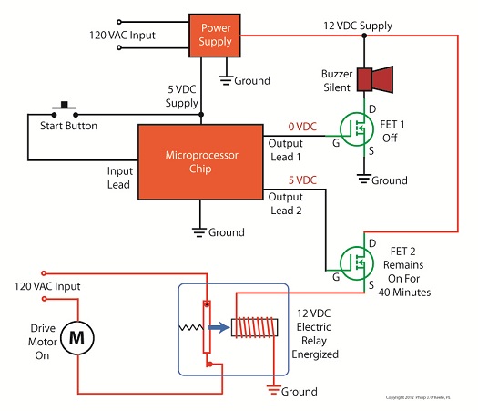
Figure 2 shows what happens after the button is depressed. The computer program is activated, directing the microprocessor chip to keep 5 VDC on Output Lead 2 and FET 2 while the prerequisite 40 minutes elapses. Thus the relay remains energized and the motor remains on during this time. Figure 3
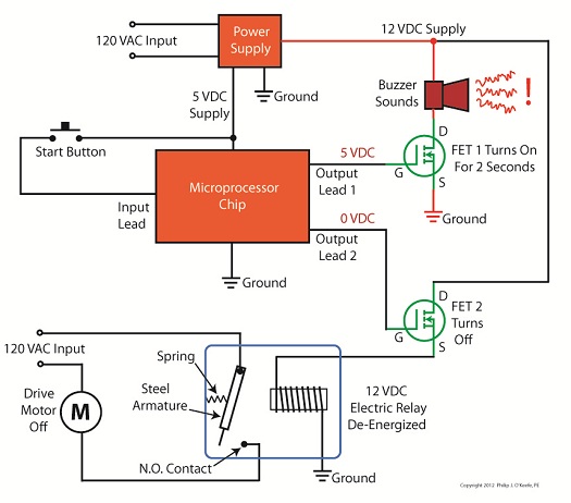
In Figure 3, at the end of the 40 minute countdown, the computer program applies 0 VDC to Output Lead 2. FET 2 then turns off the current flow to the relay and it begins to de-energize, causing the spring to pull the steel armature away from the N.O. contact and the 120 VAC power supply to be interrupted. The motor is deactivated. At the same time, the computer program applies 5 VDC to Output Lead 1 and FET 1 for 2 seconds. FET 1 turns on the flow of current through the buzzer, causing it to sound off and signal that the x-ray film processing machine is ready for use. Next time we’ll look at how transistors are used to regulate voltage within direct current power supplies like the one shown in Figure 3 above. ____________________________________________ |
Posts Tagged ‘motor control’
Transistors – Digital Control Interface, Part V
Sunday, July 15th, 2012Tags: armature, buzzer, computer program, design, electric circuit, electric drive motor, electric relay, electronic control, electronics, engineering expert witness, FET, field effect transistor, forensic engineer, industrial control, machine, microprocessor chip, microprocessor control, MOSFET, motor control, normally open contact, output lead, power supply, pushbutton, spring, transistor, voltage regulator, wire coil, x-ray film processing machine
Posted in Engineering and Science, Expert Witness, Forensic Engineering, Innovation and Intellectual Property, Personal Injury, Product Liability | Comments Off on Transistors – Digital Control Interface, Part V
Industrial Control Basics – Motor Overload Relay In Action
Sunday, March 18th, 2012|
Last week we explored the topic of thermal expansion, and we learned how the bimetal contacts in a motor overload relay distort when heated. We also discussed how the overload relay comes into play to prevent overheating in electric motor circuits. Now let’s see what happens when an overload situation occurs. Figure 1
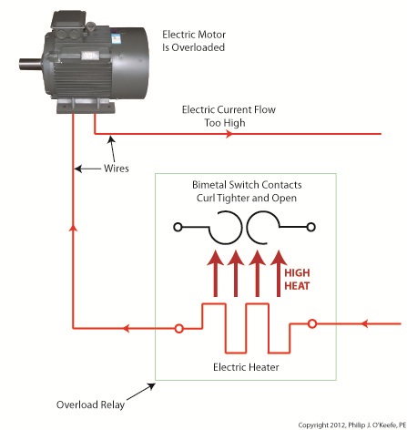
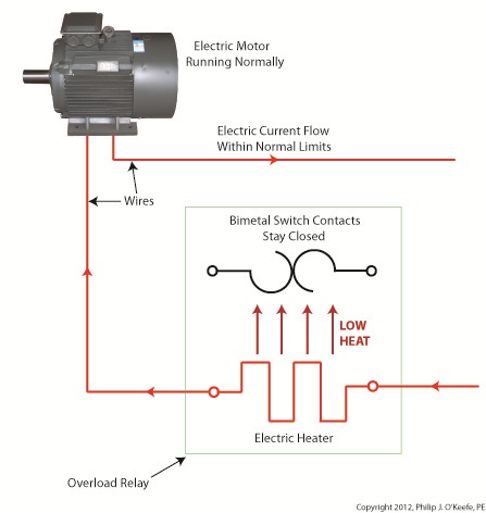
Figure 1 shows a motor becoming overloaded, as it draws in abnormally high amounts of electric current. Since this current also flows through the electric heater in the overload relay, the heater starts producing more heat than it would if the motor were running normally. This abnormally high heat is directed towards the bimetal switch contacts, causing them to curl up tightly until they no longer touch each other and open up. They will only close again when the overload condition is cleared up and the heater cools back down to normal operating temperature. Let’s now take a look at Figure 2 to see how the motor overload relay fits into our example of a conveyor belt motor control circuit. Once again, the path of electric current flow is denoted by red lines. Figure 2
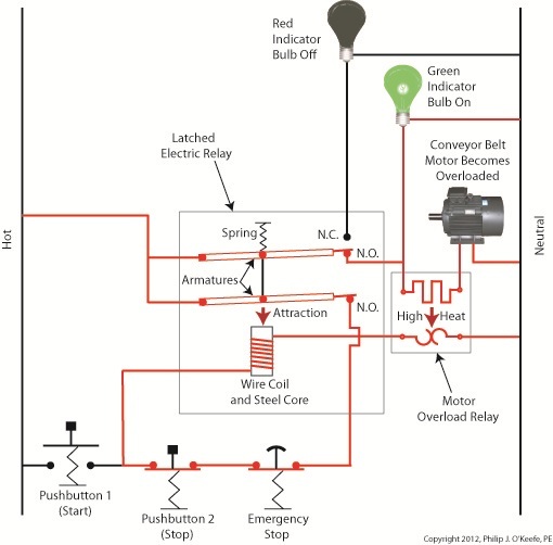
The circuit in Figure 2 represents what happens after Button 1 is depressed. That is, the electric relay has become latched and current flows between hot and neutral sides through one of the N.O. contacts along the path of the green indicator bulb, the motor overload relay heater, and the conveyor belt motor. The current also flows through the other N.O. contact, the Emergency Stop button, Button 2, the electric relay’s wire coil, and the motor overload relay bimetal contacts. The motor becomes overloaded, causing the overload relay heater to produce abnormally high heat. This heat is directed towards the bimetal contacts, also causing them to heat up. Figure 3
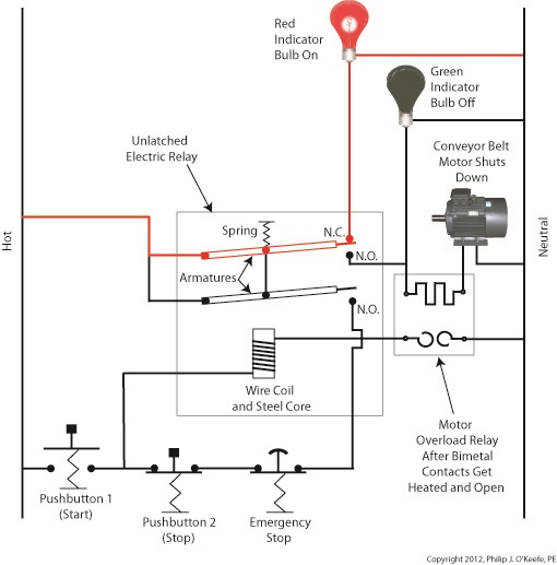
In Figure 3 the bimetal contacts have heated to the point that they have curled away from each other until they no longer touch. With the bimetal contacts open, electric current is unable to flow through to the electric relay’s wire coil. This in turn ends the magnetic attraction which formerly held the relay armatures against the N.O. contacts. The spring in the electric relay has pulled the armatures up, causing the N.O. contacts to open, simultaneously closing the N.C. contact. These actions have resulted in a loss of current to the green indicator bulb and electric motor. The red indicator bulb is now activated, and the conveyor motor is caused to automatically shut down to prevent damage and possible fire due to overheating. This means that even if the conveyor operator were to immediately press Button 1 in an attempt to restart the line, he would be prevented from doing so. Under these conditions the electric relay is prevented from latching, and the motor remains shut down because the bimetal contacts have been separated, preventing current from flowing through to the wire coil. The bimetal contacts will remain open until they once again cool to normal operating temperature. Once cooled, they will once again close, and the motor can be restarted. If the cause of the motor overload is not diagnosed and its ability to recur eliminated, the automatic shutdown process will repeat this cycle. Next time we’ll see how the overload relay is represented in a ladder diagram. We’ll also see how switches can be added to the circuit to allow maintenance staff to safely work. ____________________________________________
|
Tags: automatic control, bimetalic contacts, closed contact, controls engineer, electric current, electric relay, emergency stop, engineering expert witness, fire, forensic engineer, heater, hot, indicator bulb, industrial control, motor control, motor damage, motor overload, motor overload relay, N.C. contact, N.O. contact, neutral, normally closed contact, normally open contact, open contact, pushbutton
Posted in Engineering and Science, Expert Witness, Forensic Engineering, Innovation and Intellectual Property, Personal Injury, Product Liability, Professional Malpractice | Comments Off on Industrial Control Basics – Motor Overload Relay In Action
Industrial Control Basics – Thermal Expansion Effect on Overload Relays
Sunday, March 11th, 2012| Imagine driving on steel tires, not rubber. Don’t think it would work too well? On asphalt highways maybe not, but on the steel rails that steam locomotives travel upon, steel wheels work surprisingly well and it’s due in large part to the principles of thermal expansion and the different rates at which metal alloys expand and contract. Allow me to explain by analyzing how a locomotive“tire” is changed.
As you can imagine changing locomotive tires isn’t easy. Firstly, locomotive shop mechanics have to actually build a fire around the steel tire to heat it up. The intense heat causes its steel tire to thermally expand, meaning its steel molecules become energized by the heat and begin to vibrate. This causes the molecules to move away from each other, and this results in the tire actually growing slightly in size. This enlargement is just enough to enable mechanics to slip the tire back onto the locomotive’s wheel. Now in place, the tire is allowed to cool back down to ambient air temperatures. Cooling results in the tire’s steel molecules relaxing and moving closer to each other. The tire shrinks back to its original preheated size and tightly wraps itself around the wheel. Thermal expansion properties of metals comes into play in many other instances, including the workings of motor overload relays. Please refer to Figure 1. Figure 1
Here overload relay components are shown in the foreground box. We see that the relay includes an electric heater and a set of two peculiar looking curved objects. These are bimetal switch contacts, so named because each is made of two, that’s the “bi” part, metal strips with different thermal properties. These strips are positioned back to back, then bonded together and curved into a shape resembling a question mark. Each of the two metals has different properties, namely, one expands at a faster rate and to a greater extent than the other when heated. This differing rate of expansion is indicative of the two metals’ diverse thermal properties. When the bimetal contact is exposed to heat, one metal strip wants to expand a lot, but it is bonded to the other metal strip which only wants to expand a little. The end result is that their point of contact distorts and changes shape. When allowed to cool back down, the metal strips contract and the contact point returns to its original shape. In our next blog we’ll see how the contact shape changes and why this shape change is important. In Figure 1 the motor is running normally and there is no overload situation. Under these conditions the motor draws electric current within the normal limits of its design. That current also flows through the heater in the overload relay causing it to generate heat, but in this situation the heat change is small enough that it doesn’t affect the bimetal switch contacts and cause them to change shape. The temperature at which the switch contacts will warp depends on the overall design of the overload relay as well as its application. Next time we’ll see what part a motor overload plays in conjunction with the overload relay’s heater and bimetal contacts. ____________________________________________
|
Tags: automatic control, bimetalic contact, contract, electric current, electrical contacts, engineering expert witness, expand, forensic engineer, heater, industrial control, locomotive, locomotive tire, metal alloys, motor control, motor overload, motor overload relay, relay, steel tire, switch contacts, thermal expansion, wheel
Posted in Engineering and Science, Expert Witness, Forensic Engineering, Innovation and Intellectual Property, Personal Injury, Product Liability, Professional Malpractice | Comments Off on Industrial Control Basics – Thermal Expansion Effect on Overload Relays
Industrial Control Basics – Emergency Stops
Sunday, February 26th, 2012| Ever been in the basement when you heard a loud thud followed by a scream by a family member upstairs? You run up the stairs to see what manner of calamity has happened, the climb seeming to take an eternity. Imagine a similar scenario taking place in an industrial setting, where distances to be covered are potentially far greater and the dangerous scenarios numerous.
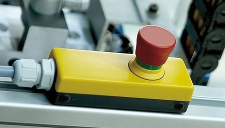
Suppose an employee working near a conveyor system notices that a coworker’s gotten caught in the mechanism. The conveyor has to be shut down fast, but the button to stop the line is located far away in the central control room. This is when emergency stop buttons come to the rescue, like the colorful example shown in Figure 1. Figure 1
Emergency stop buttons are mounted near potentially dangerous equipment in industrial settings, allowing workers in the area to quickly de-energize equipment should a dangerous situation arise. These buttons are typically much larger than your standard operational button, and they tend to be very brightly colored, making them stick out like a sore thumb. This type of notoriety is desirable when a high stress situation requiring immediate attention takes place. They’re easy to spot, and their shape makes them easy to activate with the smack of a nearby hand, broom, or whatever else is convenient. Figure 2 shows how an emergency stop button can be incorporated into a typical motor control circuit such as the one we’ve been working with in previous articles. Figure 2
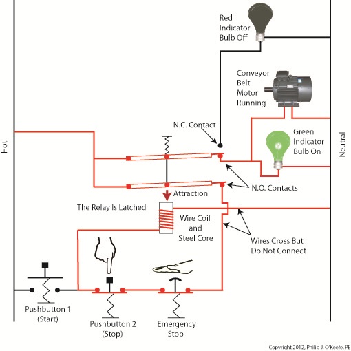
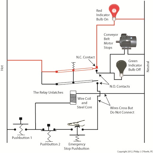
An emergency stop button has been incorporated into the circuit in Figure 2. It depicts what happens when someone depresses Button 1 on the conveyor control panel. The N.C. contact opens, and the two N.O. contacts close. The motor starts, and the lit green bulb indicates it is running. The electric relay is latched because its wire coil remains energized through one N.O. contact. It will only become unlatched when the flow of current is interrupted to the wire coil, as is outlined in the following paragraph. The red lines denote areas with current flowing through them. Both Button 2 and the emergency stop button typically reside in normally closed positions. As such electricity will flow through them on a continuous basis, so long as neither one of them is re-engaged. If either of them becomes engaged, the same outcome will result, an interruption in current on the line. The relay wire coil will then become de-energized and the N.O. contacts will stay open, preventing the wire coil from becoming energized again after Button 2 or the emergency stop are disengaged. Under these conditions the conveyor motor stops, the green indicator bulb goes dark, the N.C. contact closes, and the red light comes on, indicating that the motor is not running. This sequence, as it results from hitting the emergency stop button, is illustrated in Figure 3. Figure 3
We now have the means to manually control the conveyor from a convenient, at-the-site-of-occurrence location, which allows for a quick shut down of operations should the need arise. So what if something else happens, like the conveyor motor overheats and catches on fire and no one is around to notice and hit the emergency stop? Unfortunately, in our circuit as illustrated thus far the line will continue to operate and the motor will continue to run unless we incorporate an additional safeguard, the motor overload relay. We’ll see how that’s done next time. ____________________________________________ |
Tags: control panel, control room, conveyor, de-energize equipment, electric relay, emergency pushbutton, emergency stop button, engineering expert witness, equipment shut down, fire, forensic engineer, hot, indicator bulb, industrial control, ladder diagram, latched relay, motor control, motor control circuit, motor overheat, N.C. contact, N.O. contact, NC contact, neutral, NO contact, overload relay, push button, pushbutton, relay armature, relay coil, relay ladder logic, safeguard, unlatched relay
Posted in Engineering and Science, Expert Witness, Forensic Engineering, Innovation and Intellectual Property, Personal Injury, Product Liability, Professional Malpractice | 2 Comments »
Industrial Control Basics – Electric Motor Control
Sunday, February 19th, 2012| Electric motors are everywhere, from driving the conveyor belts, tools, and machines found in factories, to putting our household appliances in motion. The first electric motors appeared in the 1820s. They were little more than lab experiments and curiosities then, as their useful potential had not yet been discovered. The first commercially successful electric motors didn’t appear until the early 1870s, and they could be found driving industrial devices such as pumps, blowers, and conveyor belts.
In our last blog we learned how a latched electric relay was unlatched at the push of a button, using red and green light bulbs to illustrate the control circuit. Now let’s see in Figure 1 how that circuit can be modified to include the control of an electric motor that drives, say, a conveyor belt inside a factory. Figure 1
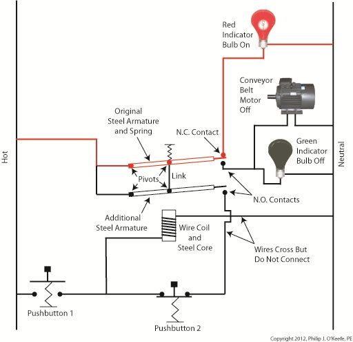
Again, red lines in the diagram indicate parts of the circuit where electrical current is flowing. The relay is in its normal state, as discussed in a previous article, so the N.O. contacts are open and the N.C. contact is closed. No electric current can flow through the conveyor motor in this state, so it isn’t operating. Our green indicator bulb also does not operate because it is part of this circuit. However current does flow through the red indicator bulb via the closed N.C. contact, causing the red bulb to light. The red and green bulbs are particularly useful as indicators of the action taking place in the electric relay circuit. They’re located in the conveyor control panel along with Buttons 1 and 2, and together they keep the conveyor belt operator informed as to what’s taking place on the line, such as, is the belt running or stopped? When the red bulb is lit the operator can tell at a glance that the conveyor is stopped. When the green bulb is lit the conveyor is running. So why not just take a look at the belt itself to see what’s happening? Sometimes that just isn’t possible. Control panels are often located in central control rooms within large factories, which makes it more efficient for operators to monitor and control all operating equipment from one place. When this is the case, the bulbs act as beacons of the activity taking place on the line. Now, let’s go to Figure 2 to see what happens when Button 1 is pushed. Figure 2
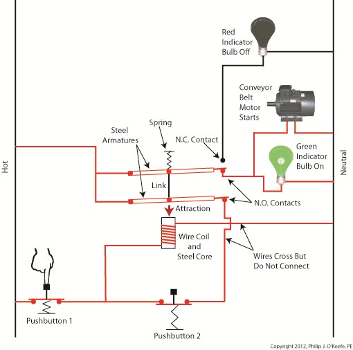
The relay’s wire coil becomes energized, causing the relay armatures to move. The N.C. contact opens and the N.O. contacts close, making the red indicator bulb go dark, the green indicator bulb to light, and the conveyor belt motor to start. With these conditions in place the conveyor belt starts up. Now, let’s look at Figure 3 to see what happens when we release Button 1. Figure 3
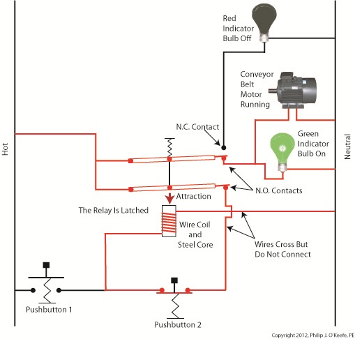
With Button 1 released the relay is said to be “latched” because current will continue to flow through the wire coil via one of the closed N.O. contacts. In this condition the red bulb remains unlit, the green bulb lit, and the conveyor motor continues to run without further human interaction. Now, let’s go to Figure 4 to see how we can stop the motor. Figure 4
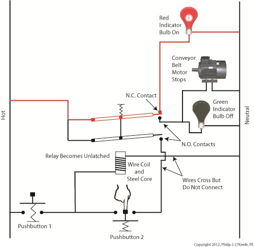
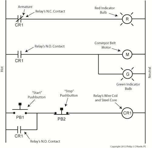
When Button 2 is depressed current flow through the relay coil interrupted. The relay is said to be unlatched and it returns to its normal state where both N.O. contacts are open. With these conditions in place the conveyor motor stops, and the green indicator bulb goes dark, while the N.C. contact closes and the red indicator bulb lights. Since the relay is unlatched and current no longer flows through its wire coil, the motor remains stopped even after releasing Button 2. At this point we have a return to the conditions first presented in Figure 1. The ladder diagram shown in Figure 5 represents this circuit. Figure 5
Next time we’ll introduce safety elements to our circuit by introducing emergency buttons and motor overload switches. ____________________________________________ |
Tags: blower, closed contact, control panel, control room, conveyor belt, electric current flow, electric motor, electric relay, engineering expert witness, equipment operator, factory, forensic engineer, indicator lamp, industrial control, ladder diagram, latched circuit, motor control, motor drive, N.C., N.O., normal state, normally closed, normally open, panel indicator, pump, push button, safety, start pushbutton, stop pushbutton
Posted in Engineering and Science, Expert Witness, Forensic Engineering, Innovation and Intellectual Property, Personal Injury, Product Liability, Professional Malpractice | Comments Off on Industrial Control Basics – Electric Motor Control
Industrial Control Basics – Pushbuttons
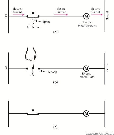
Monday, December 26th, 2011Tags: control system, current flow, electric motor, electrical circuit, engineering expert witness, forensic engineer, hot, industrial control, ladder diagram, machine control, mechanized equipment, motor control, neutral, normally closed, normally open, pushbutton, relay, spring, switch
Posted in Engineering and Science, Expert Witness, Forensic Engineering, Innovation and Intellectual Property, Personal Injury, Product Liability, Professional Malpractice | Comments Off on Industrial Control Basics – Pushbuttons
Industrial Control Basics – Ladder Diagrams
Sunday, December 18th, 2011| The other day I pressed the button to activate my electric garage door opener and nothing happened. I pushed again and again, still nothing. Finally, I convinced myself to get out of the car and take a closer look. A wooden board I had propped up against the side of the garage wall had come loose, wedging itself in front of the electric eye, you know, the one that acts as a safety. The board was an obstruction to the clear vision of the eye. It couldn’t see the light emitter on the other side of the door opening and wouldn’t permit the door opener to function.
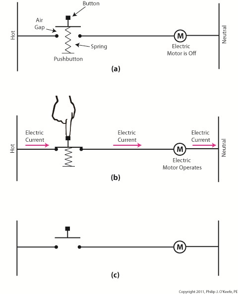
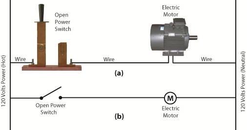
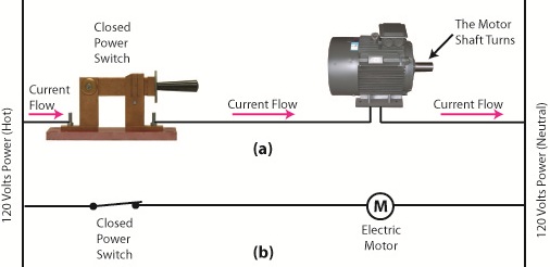
The basic manual control system we looked at last week operates similarly to the eye on a garage door opener. If you can’t “close the loop,” you won’t get the power. Last week’s example was as basic as things get. Now let’s look at something a bit more complex. Words aren’t always the best vehicle to facilitate understanding, which is why I often use visual aids in my work. In the field of industrial control systems diagrams are often used to illustrate things. Whether it’s by putting pencil to paper or the flow diagram of software logic, illustrations make things easier to interpret. Diagrams such as the one in Figure l are often referred to as “ladder diagrams,” and in a minute we’ll see why. Figure 1 Figure 1(a) shows a basic manual control system. It consists of wires that connect a power switch and electric motor to a 120 volt alternating current power source. One wire is “hot,” the other “neutral.” The hot side is ungrounded, meaning that it isn’t electrically connected to the Earth. The neutral side is grounded, that’s right, it’s driven into the ground and its energy is dissipated right into the earth, then returned back to the power grid. In Figure 1(a) we see that the power switch is open and an air gap exists. When gaps exist, we don’t have a closed electrical loop, and electricity will not flow. Figure 1(b), our ladder diagram, aka line diagram, shows an easier, more simplified representation of the manual control shown in Figure 1(a). It’s easier to decipher because there’s less going on visually for the brain to interpret. Everything has been reduced to simple lines and symbols. For example, the electric motor is represented by a symbol consisting of a circle with an “M” in it. Now, let’s turn our attention to Figure 2 below to see what happens when the power switch is closed. Figure 2 The power switch in Figure 2(a) is closed, allowing electric current to flow between hot and neutral wires, then power switch, and finally to the motor. The current flow makes the motor come to life and the motor shaft begins to turn. The line diagram for this circuit is shown in Figure 2(b). You might have noticed that the line diagrams show in Figures 1(b) and 2(b) have a rather peculiar shape. The vertically running lines at either side depict the hot and neutral legs of the system. If you stretch your imagination a bit, they look like the legs of a ladder. Between them run the wires, power switch, and motor, and this horizontal running line represents the rung of the ladder. More complicated line diagrams can have hundreds, or even thousands of rungs, making up one humongous ladder, hence they are commonly referred to as ladder diagrams. Next week we’ll take a look at two key elements in automatic control systems, the push button and electric relay, elements which allow us to do away with the need for human intervention. ____________________________________________ |
Tags: automatic control, electric circuit, electric current, electric motor, electric relay, electric utility, engineering expert witenss, forensic engineer, ground, hot, industrial control, ladder diagram, ladder logic, line diagram, manual control, motor control, neutral, power flow, power grid, power switch, push button, visual aid, wires
Posted in Courtroom Visual Aids, Engineering and Science, Expert Witness, Forensic Engineering, Innovation and Intellectual Property, Personal Injury, Product Liability, Professional Malpractice | Comments Off on Industrial Control Basics – Ladder Diagrams
