|
Happy Holidays from EngineeringExpert.net, LLC and the Engineering Expert Witness Blog. Pulleys Make Santa’s Job Easier
Copyright 2016 – Philip J. O’Keefe, PE Engineering Expert Witness Blog ____________________________________ |

|
Happy Holidays from EngineeringExpert.net, LLC and the Engineering Expert Witness Blog. Pulleys Make Santa’s Job Easier
Copyright 2016 – Philip J. O’Keefe, PE Engineering Expert Witness Blog ____________________________________ |
|
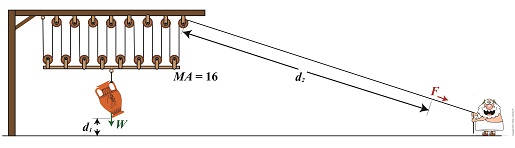
We’re all familiar with the phrase, “too much of a good thing.” As a professional engineer, I’ve often found this to be true. No matter the subject involved, there inevitably comes a point when undesirable tradeoffs occur. We’ll begin our look at this phenomenon in relation to compound pulleys today, and we’ll see how the pulley arrangement we’ve been working with encounters a rope length tradeoff. Today’s arrangement has a lot of pulleys lifting an urn a short distance. We’ll be working with two distance/length factors and observe what happens when the number of pulleys is increased. Last time we saw how the compound pulley is essentially a work input-output device, which makes use of distance factors. In our example below, the first distance/length factor, d1, pertains to the distance the urn is lifted above the ground. The second factor, d2, pertains to the length of rope Mr. Toga extracts from the pulley while actively lifting. It’s obvious that some tradeoff has occurred just by looking at the two lengths of rope in the image below as compared to last week. What we’ll see down the road is that this also affects mechanical advantage. The compound pulley here consists of 16 pulleys, therefore it provides a mechanical advantage, MA, of 16. For a refresher on how MA is determined, see our preceding blog.
Rope Length Tradeoff in a Compound Pulley
With an MA of 16 and the urn’s weight, W, at 40 pounds, we compute the force, F, Mr. Toga must exert to actively lift the urn higher must be greater than, F > W ÷ MA F > 40 Lbs. ÷ 16 F > 2.5 Lbs. Although the force required to lift the urn is a small fraction of the urn’s weight, Mr. Toga must work with a long and unwieldy length of rope. How long? We’ll find out next time when we’ll take a closer look at the relationship between d1 and d2. Copyright 2016 – Philip J. O’Keefe, PE Engineering Expert Witness Blog ____________________________________ |
|
Last time we touched on the fact that bigger is better when it comes to using a rangefinder to measure extremely long distances. Today we’ll expand on that theme and discover how bigger is indeed more accurate. Returning to our previous example, we’re still trying to find the distance to that ship on the horizon. We’ve got two rangefinders at our disposal, one short, one long, and the measurements provided by them are vastly different. Which is correct? To find out, we’ll hypothesize that we’ve taken the time to meticulously measure the distance the hard way, with a really long tape measure. Doing so, we find the actual distance to the ship is 5280 feet. We can now compare the actual measured distance to the measurements taken with our two rangefinders and compare their accuracy: Rangefinder One = 5729 feet – 5280 feet = 449 feet Rangefinder Two = 5208 feet – 5280 feet = -72 feet
The smaller rangefinder results in a difference, or error, of 449 feet, while the bigger results in a difference of 72 feet. It’s clear that the bigger rangefinder gets us closer to the actual measurement taken by tape measure, so it’s the most accurate.
The obvious conclusion is that the bigger the rangefinder used, the smaller the error factor. That’s because as the length of the rangefinder increases, the smaller the angle θ becomes, a situation which results in the tangent of θ moving farther away from rather than closer to 90°, all of which translates to more accuracy in our rangefinder’s measurements. Put another way, the bigger the rangefinder, the less likelihood there is of its angle θ‘s tangent hovering near 90° and becoming asymptotic, an undesirable outcome for reasons explained in a previous blog in this series. Next time we’ll see how early astronomers were able to arrive at relatively accurate calculations of the distances between Earth and other heavenly bodies by using the parallax effect produced by the world’s largest optical rangefinder, Planet Earth itself. ____________________________________
|
|
Ever wondered if a running horse lifts all four of its feet off the ground at the same time? Leland Stanford, an industrialist and horseman of the late 19th Century did, and he hired photographer Eadweard Muybridge to find out. Muybridge’s series of 24 photographs of Stanford’s horse, Sallie Gardner, came to be known as Sallie Gardner at a Gallop and is regarded to be an early example of silent film.
The Muybridge photos were viewed at increased speed on a zoopraxiscope, a device he invented in 1879. A precursor to modern movie projectors, it projected a series of independent photographs as a moving image through the use of multiple cameras shooting the subject at different points in time. In this way it was disclosed that yes, indeed, there were moments when all four of a galloping horse’s feet hover in mid air. Today’s moving images are displayed at between 24 and 300 fps, depending on the application. Muybridge’s experiment proved that not only are moving images more engaging than static ones, they are also more explicit, able to convey information still images are not. Take for example this series of stills of a centrifugal clutch assembly.
Are you able to tell by looking at these two-dimensional images how a clutch works? How as the engine speeds up the spinning shoes move out and make contact with the clutch housing, this pressure causing the entire assembly to spin? Unless you’re familiar with clutches, probably not. Now here’s the same clutch brought to life through animation:
In today’s fast paced, internet-laden society, people’s attention spans are shorter than ever, and their demands to be visually engaged are high. It’s been proven that holding a modern day viewer’s attention for more than three seconds is a difficult task. This truth is evident in the courtroom as well, where trial attorneys are obliged to increase the production value of evidence presented in order to win over juries, and animation is becoming their tool of choice. What held true more than 100 years ago still holds true today: Nothing tells a story like a moving image. Next time we’ll switch gears, quite literally, to understand how a series of gears work together to power machinery. ________________________________________ Note: If you are viewing this blog article in an email and the animation video does not appear, then click on this link to view the article with your web browser. ________________________________________ |
| Last week we began our discussion on perception and how without visual cues individuals exposed to the same verbal information will oftentimes arrive at different conclusions as to what they just heard. We also touched on the fact that peoples’ attention spans are extremely limited, so much so that experts studying human behavior conclude that even when the subject matter is extremely interesting to the listener, their ability to absorb information is limited to mere minutes.
No one would argue the fact that we live in the Visual Age. Most images are flashed at us for only a few seconds. Our appetites for visual arousal seem never to be satiated, and venues that lack a visual component are suffering shrinking audiences. Orchestras come to mind. Even pop stars and professional sporting events today employ huge screens to “up” their visual content in the hopes of keeping their audiences engaged. This phenomenon was addressed way back in 1982, when the internet and its cornucopia of images was just a baby. Dr. Donald E. Vinson, a leader in courtroom behavior and trial strategy, wrote in the March, 1982 edition of Trial Magazine, “Attention span and the arousal of attention are fundamental to all perception,” a sentiment which Benjamin Franklin echoed in his statement, “If you would persuade, you must appeal to interest rather than intellect.” Dr. Vinson also states that, “Perceptions are constantly subject to emotional reinforcement, and those which are positively reinforced will tend to be better remembered.” And what’s supplying these necessary emotional reinforcements? Stimulation to the senses. And what type of stimulation is most effective? In Dr. Vinson’s opinion, “A moving stimulus is also more effective than a static one.” So will shortened modern-day attention spans result in speed trials that are equivalent to short movies? Anything is possible, but our legal system as it stands today isn’t able to produce this just yet. So how is an attorney trying to impress their message upon jurors from diverse backgrounds and life experience going to succeed in getting their message across? And what if that message is complicated and requires certain technical aptitudes? Will verbal descriptions be enough? Considering the fact that the average adult American reads at or below the 5th grade reading level, it is unlikely. Research findings discovered more than 30 years ago still hold true today. Messages are most effectively received when employing visual cues, and the most effective visual cue is one that moves. There’s a good reason why my blogs seldom lack a visual component… ___________________________________________
|
|
Ever play that game as a kid where you whisper something in the next kid’s ear, and she whispers it to the next kid, and on down the line? When the first and last kids’ renditions of what was whispered are compared, they’re vastly different. Part of the reason for this is that when whispering from ear to ear no visual cues as to the message’s content are present.
There’s a reason that the world’s leading language learning systems use visual images to facilitate learning. It’s the same reason that individuals who move to a foreign country can quickly acquire the new language. Visual cues inform the brain in a way that words alone cannot. Words and images are intimately linked within the human brain. If only words are employed, perceptions are bound to be less than exact between individuals. This can present a problem in the courtroom, when the precision of received messages is of the most crucial importance. How can attorneys address this problem to produce a message which has the highest likelihood of being perceived identically by all jurors? By delivering their message through visual images. Studies show that when visual images are provided, perception between individuals is more uniform. Several weeks ago a two dimensional (2D) patent drawing was introduced in our blog series. Granted, it was a visual image, and yet a complete understanding of how the machine actually operated remained a mystery to most. Then we transformed that 2D image into an attention-grabbing 3D animation. By doing so, all gaps in understanding were closed. Sometimes, particularly with complex things, only a moving representation will provide the required clarity. Next week we’ll further examine how limitations in perception affect what goes on in the courtroom. In the meantime I invite you to ponder the impact of this statement, made by the country’s leading authority in the field of jury behavior and trial strategy, Dr. Donald E. Vinson: “Several studies on attention span indicate that even persons who are intensely interested in the topic at hand cannot maintain a high level of attention for more than 20 minutes.” ___________________________________________ |
|
Movies, that is 3D animations, are moving into the courtroom, and intended messages are made clearer than ever as a result. If a picture is worth a thousand words, how much more effective is a moving 3D image? We’ve been viewing a static two-dimensional representation of a machine for the past two blogs. Have you been able to figure it out yet? Here it is again:
Would it help you to understand if I identified it as a piece of food manufacturing equipment equipped with a rake that aligns cookies on a conveyor belt? Would that verbal description allow you to “see” in your mind’s eye how it operates? Unless you had the right technical background, it’s unlikely. Last week we introduced the verbiage person of ordinary skill in the art as a term widely used within patent litigation. This person is said to have the ability to interpret and understand patent drawings, and they typically possess a technical and/or scientific background. But what if participants in a legal proceeding lack this background? Technical experts are often hired on as consultants to attorneys, and in some instances, judges, when clarification is required. These experts provide technical expertise and tutorials on the technology involved in complex cases, and it happens with regularity when the operation of a patented device is in question. By employing 3D animations the expert can show how the device operates, rather than attempt to explain it using the technical language of their profession. The expert works closely with an animation artist to create the animation, providing the technical information that the animator will use to create the fully functional model. Animators do not typically have the technical background to accomplish this on their own and will require an ongoing dialog with the technical expert to create the animation. And now the moment we’ve all been waiting for. Here is our static image brought to life through animation:
The animation commands the viewer’s attention and holds their interest, even if they have no background in engineering or science, and the device’s function is now made clear. It must be noted that in the patent drawing, part of the mechanism lies in front of a steel divider plate and part behind, but for purposes of clarity the entire mechanism has been shown to the front of the plate. Now there’s no doubt as to how the parts move together to even up the rows of cookies on the conveyor belt. Next week we’ll talk about juries, perception, and the advantages of using courtroom animations when at trial. |
|
I remember the first time I saw a blueprint. It was during high school shop class where we learned how to use power tools to make the wooden chairs, tables, and chests shown in blueprints. I was completely confused. The odd paper and blue print, coupled with the liberal use of unfamiliar symbols, dashes and dots, and what appeared to be a mind boggling amount of detail was enough to start me in a cold sweat. For many people, patent drawings are a lot like that first blueprint I saw. As a static two-dimensional (2D) representation of an operational device which is often complex, they present an immense amount of information on a page. The average person would be hard pressed to interpret them, and in fact, as we’ll learn later, they aren’t supposed to be able to. We’ve been talking about patent basics in this series of blogs, and we’ll continue that discussion in the following weeks with a concentration on patent drawings. In the meantime, here’s one to ponder. When you look at a patent drawing like the one below, what do you see? What do you think this thing is and what is it supposed to do? We’ll find out next week…
___________________________________________ |
|
We’ve been discussing hurtles which must be jumped in order for an inventor’s creation to be considered for a patent. Federal statutes, namely 35 USC § 101, define the bases of patentability, including providing definitions on key terms, such as what constitutes a machine, an article of manufacture, and a composition of matter. Today we’ll wrap up our discussion on determining patent eligibility when we explore the final hurtle by defining process. To get an understanding of what is meant by process, we must look to the lawsuit of Gottschalk v. Benson, a case involving patentability of a mathematical algorithm within a computer program. In this case the US Supreme Court held that a process is a series of steps or operations that transform substances or came about by way of a newly invented machine. Based on the Court’s definition, a process can be many things, from a production line that transforms corn into corn chips within a food manufacturing plant to a mathematical algorithm running within software on the platform of a newly devised type of computer. However, the term usually pertains to a series of operations or steps, most frequently manufacturing in nature, where physical substances are transformed into useful products, that is, they possess the quality of utility, as discussed earlier in this blog series. A “physical substance” is anything of a physical nature existing on our planet.
Before I end this series I’d like to mention that under 35 USC § 101 an invention can be eligible for a patent if it makes a useful and beneficial improvement to an existing machine, article of manufacture, composition of matter, or process. That is to say, something may have already been patented which performs a specific function, but if that is improved upon in any significant way, it may receive a new patent. For example, suppose an improved process for manufacturing food products was developed by adding additional steps to an existing patented process. If this improvement results in benefits such as lowered production costs, increased production rate, or reduced health risks to consumers, then this improved process may be eligible for a patent under 35 USC § 101. Next time we’ll begin an exploration of the growing presence of 3D animations within the courtroom, specifically how they bring static 2D patent drawings to life. ___________________________________________ |
| The other day I pressed the button to activate my electric garage door opener and nothing happened. I pushed again and again, still nothing. Finally, I convinced myself to get out of the car and take a closer look. A wooden board I had propped up against the side of the garage wall had come loose, wedging itself in front of the electric eye, you know, the one that acts as a safety. The board was an obstruction to the clear vision of the eye. It couldn’t see the light emitter on the other side of the door opening and wouldn’t permit the door opener to function.
The basic manual control system we looked at last week operates similarly to the eye on a garage door opener. If you can’t “close the loop,” you won’t get the power. Last week’s example was as basic as things get. Now let’s look at something a bit more complex. Words aren’t always the best vehicle to facilitate understanding, which is why I often use visual aids in my work. In the field of industrial control systems diagrams are often used to illustrate things. Whether it’s by putting pencil to paper or the flow diagram of software logic, illustrations make things easier to interpret. Diagrams such as the one in Figure l are often referred to as “ladder diagrams,” and in a minute we’ll see why.
Figure 1 Figure 1(a) shows a basic manual control system. It consists of wires that connect a power switch and electric motor to a 120 volt alternating current power source. One wire is “hot,” the other “neutral.” The hot side is ungrounded, meaning that it isn’t electrically connected to the Earth. The neutral side is grounded, that’s right, it’s driven into the ground and its energy is dissipated right into the earth, then returned back to the power grid. In Figure 1(a) we see that the power switch is open and an air gap exists. When gaps exist, we don’t have a closed electrical loop, and electricity will not flow. Figure 1(b), our ladder diagram, aka line diagram, shows an easier, more simplified representation of the manual control shown in Figure 1(a). It’s easier to decipher because there’s less going on visually for the brain to interpret. Everything has been reduced to simple lines and symbols. For example, the electric motor is represented by a symbol consisting of a circle with an “M” in it. Now, let’s turn our attention to Figure 2 below to see what happens when the power switch is closed.
Figure 2 The power switch in Figure 2(a) is closed, allowing electric current to flow between hot and neutral wires, then power switch, and finally to the motor. The current flow makes the motor come to life and the motor shaft begins to turn. The line diagram for this circuit is shown in Figure 2(b). You might have noticed that the line diagrams show in Figures 1(b) and 2(b) have a rather peculiar shape. The vertically running lines at either side depict the hot and neutral legs of the system. If you stretch your imagination a bit, they look like the legs of a ladder. Between them run the wires, power switch, and motor, and this horizontal running line represents the rung of the ladder. More complicated line diagrams can have hundreds, or even thousands of rungs, making up one humongous ladder, hence they are commonly referred to as ladder diagrams. Next week we’ll take a look at two key elements in automatic control systems, the push button and electric relay, elements which allow us to do away with the need for human intervention. ____________________________________________ |