| When I was a kid I remember how cool it was to have a headlight on my bike. Unlike the headlights that the other kids had, mine was not powered with flashlight batteries. The power came from a little gadget with a small wheel that rode on the front tire. As I pedaled along, the tire’s spinning caused the small wheel to spin, and voila, the headlight bulb came to life. Little did I know that this gadget was a simple form of electrical generator, and of course I was oblivious to the fact that a similar device, albeit on a much larger scale, was being used at a nearby power plant to send electricity to my home.
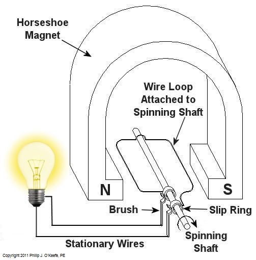
Over the last few weeks we learned how a coal fired power plant transforms chemical energy stored in coal into heat energy and then into mechanical energy which enables a steam turbine shaft to spin. We’ll now turn our attention to the electrical generator. It’s responsible for performing the last step in the energy conversion process, that is, it converts mechanical energy from the steam turbine into the desired end product, electrical energy for our use. It represents the culmination in energy’s journey through the power plant, the process by which energy contained in a lump of coal is transformed into electricity. To show how this final energy conversion process works, let’s look at Figure 1, a simplified illustration of an electrical generator. Figure 1 – A Basic Electrical Generator You’ll note that the generator in our illustration has a shaft with a loop of wire attached to it. When the shaft spins, so does the loop. The shaft and wire loop are placed between the north (N) and south (S) poles of a horseshoe magnet. It’s a permanent magnet, so it always has invisible lines of magnetic flux traveling between its two poles. These magnetic lines of flux are the same type as the ones created by kids’ magnets, when they play with watching paperclips jump up to meet the magnet. The properties of magnets are not completely understood, even to adults who work with them every day. And what could be more mysterious than the fact that as the shaft and wire loop spin through the lines of magnetic flux in the generator, an electric current is produced in the wire loop. Now, this current that’s flowing through the spinning wire loop is of no use if we can’t channel it out of the generator. The wire loop is spinning vigorously, so you can’t directly connect the ends of the loop to stationary wires. A special treatment is required. Each end of the loop is connected to a slip ring. A part called a “brush” presses against each slip ring to make electrical contact. The electrical current then flows from the loop through the spinning slip rings, through the brushes, and into the stationary wires. So, if, for example, a light bulb is connected to the other end of the stationary wires, this completes an electric circuit through which current can flow. The light bulb will glow as long as the generator shaft keeps spinning and the wire loop keeps passing through the magnetic lines of flux from the magnet. So we see that the key to the whole energy conversion process is to have movement between magnetic lines of flux and a loop of wire. As long as this movement occurs, the electricity will flow. This basic principle is the same in a coal fired power plant, but the electrical generator is far more complicated in construction and operation than shown here. My Coal Power Plant Fundamentals seminar goes into far greater detail on this and other aspects of electricity generation, but what I have shared with you above will give you a basic understanding of how they operate. That concludes our journal with coal through the power plant. This series of blogs has, you will remember, presented a simplified version of the complex material presented in my teaching seminars. Next week we’ll branch off, taking a look at why electrical wires come in different thicknesses. _____________________________________________
|
Posts Tagged ‘power plant’
Coal Power Plant Fundamentals – The Generator
Monday, March 7th, 2011Transformers – Electric Utility Power Savers
Sunday, January 2nd, 2011| Each day millions of Americans start their mornings with coffee, brewed in a coffee maker, and a microwaved breakfast. They flick on the light and exhaust fan before starting their showers and blow dry their hair afterwards. Each of these acts of modern living is a small miracle. And if you’re like most people you can’t see the power plant supplying the power to your modern conveniences from your home, and how the electricity travels from the plant to you isn’t too clear.
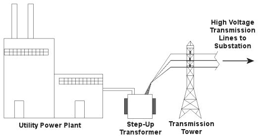
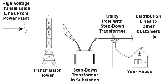
Truth is the process of supplying our homes with power isn’t as straightforward as you might think, and the actual transmission of that power isn’t straightforward at all. To begin with, the wires used in power lines are less than perfect conductors of electricity. Along any given length of wire there are all sorts of imperfections in the metal, and these tend to resist the flow of electrical current. These imperfections will always exist to some extent, even with the best manufacturing techniques and quality control, and the longer the power line, the more resistance the power flow will meet. The result is loss of electrical power. If there weren’t some kind of compensatory action at work to rectify this, your morning routine wouldn’t be nearly so smooth. To address the problem of power loss electric utilities use step-up transformers, similar to the one in Figure 1. This enables voltage produced by the generator at the plant to be raised to a higher voltage, in turn enabling it to travel longer distances and remain effective. Figure 1 – Electricity Leaving the Power Plant Goes Through a Step-Up Transformer For example, let’s say that an electric generator puts out 12,000 volts, and a step-up transformer raises that to 765,000 volts, enabling transmission to customers far away. If you will recall from last week’s blog, with electrical transformers, there is an inverse relationship between voltage and current. So, when a step-up transformer increases input voltage, it actually results in a lowering of electrical current. So how does this phenomenon aid in power transmission? Simply put, when there is less current flowing through the wires, there is an accompanying reduction in power loss over the long length of the transmission line. Let’s take a look at what happens when the power reaches our homes. Figure 2 shows a simplified distribution route from the power plant. Figure 2 – A Step-Down Transformer is Used to Supply Electric Utility Customers First, the higher voltage originating from the step-up transformer at the power plant is decreased by the use of a step-down transformer located in a substation many miles away at the other end of the transmission line. The use of this intermediary step-down transformer effectively lowers the voltage and at the same time raises the current at the other end of the line, the end where customers like you and I are waiting to use our hair dryers unimpeded. The path that the power follows is somewhat circuitous, but well planned out, with numerous strategically positioned distribution lines acting as the final leg of delivery. These distribution lines do what their name implies, they weave their way along streets and alleys, finally distributing electricity to customers. A step-down transformer located in a substation along the power transmission route allows this all to happen. It can readily convert the 765,000 volts being sent by the power plant to the 25,000 volts needed to feed distribution power lines. These, in turn, power individual homes, hospitals, etc. Now you obviously can’t plug a television into a 25,000 volt wall outlet located in your house, so another step-down transformer is required to temper it into power that’s both usable and safe. The one in our diagram is mounted on a nearby utility pole, and its job is to lower the 25,000 volts which it receives into a more manageable 240 and 120 volts, which is then fed into your home. That wraps up our series on electrical transformers. Perhaps the next time you flip that switch in your home, whether it be on your hair dryer, TV, or what have you, you’ll pause for a moment to reflect on the long path it has followed to make your life just a little bit easier. _____________________________________________
|
Transformers – The Voltage/Current Trade-Off
Sunday, December 26th, 2010|
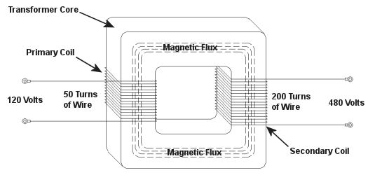
As a child I considered the reindeer Rudolph, with his nose so bright, to be a marvel of engineering. Now an adult, I remain perplexed as to the mystery behind the self-generating power source behind his nose. Did it ever overheat? I wondered. Perhaps today’s discussion can shed some light on the matter. During the course of our discussion of electricity certain terms have been tossed about, like voltage and current. For some the distinction between the two may be unclear, and that is what we’ll be addressing today. Electricity is a rather abstract phenomenon, but you may consider the flow of electrical current through a wire to be much like water flowing through a garden hose. The water won’t flow unless there’s sufficient pressure behind it, and that pressure is supplied by pumps, either at your city water works or your personal well. Take away the pressure, and the water stops flowing through the hose. Electricity flows in much the same manner. It requires a pushing pressure to get it on its journey from power plant to home, and that pressure is voltage. Take away voltage, and the current stops flowing through the wire. Voltage is, of course, produced by an electrical generator at the power plant. Last time we saw how an electrical transformer can reduce high voltage to low voltage and how this process also works in reverse. But how can that be? How can low voltage be turned into high? Is it really possible to get “something from nothing”? Let’s take a closer look. When a light bulb burns out in your home, you routinely look at the bulb to see how many watts it is so you can replace it with the same type. But what exactly is a “watt”? It’s a unit of power, and the markings on the bulb tell you how much electrical power it consumes when you use it. Generally speaking, this electrical power is related to voltage and current by this formula: Power = Volts × Electrical Current Knowing this, if I have a 60 watt bulb in a table lamp, and I plug it into a 120 volt wall outlet, then how much electrical current is the lamp going to draw from the outlet? Using the formula above and a little algebra, we get: Electrical Current = Power ÷ Volts Electrical Current = 60 watts ÷ 120 volts = 0.5 amperes And believe it or not, this same formula that’s used to assess power of a light bulb also applies to electrical transformers. Basically, the power going into the transformer is equal to the power coming out. To see how this works, consider the example step-up transformer shown in Figure 1, which converts a low voltage to a higher one. By the way, “step up” transformers have all sorts of applications. For example, they are used by electric utilities to raise the voltage produced by a power plant to make it more economical to transmit to far away customers. We’ll get into that in another article. Figure 1 – A Step-Up Transformer In this example the input voltage on the primary coil is stepped up from 120 volts to 480 volts on the secondary coil, and this works according to the formula we learned about in last week’s blog: NP ÷ NS = VP ÷ VS where NP and NS are the number of turns of wire in the primary and secondary coils respectively, and VP and VS are the voltages of the primary and secondary coils respectively. Plugging in the numbers we get: 50 turns ÷ 200 turns = 120 volts ÷ VS [(200 turns ÷ 50 turns) × 120 volts] = VS = 480 volts Okay, for the sake of our example let’s say that an electric motor is connected to the 480 volt secondary coil. We have an electric meter hooked up to the primary coil and we measure a 2 ampere (a.k.a. “amps”) electrical current flowing through it. Without having the benefit of another electric meter positioned at the secondary coil, how can we measure how much electrical current is flowing through it? The current flowing through the secondary coil is found by equalizing the power in the primary and secondary coils: PowerP = PowerS Another way of stating this is to say that electrical power is equal to volts times current, so the equation becomes: VP × IP = VS × IS where IP and IS are the primary coil and secondary coil currents, respectively. Plugging in the numbers and working a little algebra we get the electrical current in the secondary coil: 120 volts × 2 amps = 480 volts × IS IS = (120 volts × 2 amps) ÷ 480 volts = 0.5 amps This shows us that the current flowing in the secondary coil is lower than that of the primary coil. It is therefore obvious that the voltage increase in the secondary coil comes at the expense of electrical current that can flow through the secondary coil. Squeeze down on current, voltage goes up. Squeeze down on voltage, current goes up. The power flowing through the transformer stays the same. Conversely, step-down transformers reduce the voltage coming in, and thereby produce the reverse effect. There is an actual increase in current that can flow through the secondary coil. This principle exemplifies the tradeoff process which is often present in science and engineering. Next time we’ll explore how both step-up and step-down transformers are used by electric utilities to transmit power from power plants to its customers tied into the utility grid. As for Rudolph and his power source, that’s still under investigation. _____________________________________________
|
Sound and Exposure Standards
Sunday, November 14th, 2010|
How many crickets clicking their legs together in unison would it take before we would suffer hearing loss at the sound exposure? Would we need to sit in a garden filled with millions of them all night long, only to discover in the morning that we could no longer hear the tea kettle’s whistle? The chart below may not provide the answer to this question, but it does provide some very good examples of different sounds and the point at which they become hazardous. So how do we know where we’re at safety-wise with sound pressure levels and exposure times? This question wasn’t pondered until the 1950s, when the military, specifically the Air Force, provided the first standards in this regard in 1956. This initial action was followed up by numerous studies and standards committees wrestling with the issue. It wasn’t until 1981 that the Occupational Health and Safety Administration (OSHA) required employers to implement hearing conservation programs for employees in certain noise-filled environments. What surprised many of the first scientists studying the impact of sound is that sounds don’t necessarily have to be initially perceived as “too loud” in order to cause hearing loss. Many sounds that we perceive as easily tolerated can in fact cause hearing damage if exposure is long enough. So what’s “long enough?” Title 29 of the Code of Federal Regulations, Section 1910.95, lists the OSHA permissible sound exposure durations at various sound levels, as shown in Table 1. |
| Duration of Exposure (Hrs.) | Sound Level (dB) |
| 8 | 90 |
| 6 | 92 |
| 4 | 95 |
| 3 | 97 |
| 2 | 100 |
| 1.5 | 102 |
| 1 | 105 |
| 0.5 | 110 |
| 0.25 or less | 115 |
Table 1 – OSHA Permissible Noise Exposures
|
Just to put things into perspective, a small chain saw tearing into a log typically produces sound at 90dB, or 90 decibels, which you will recall from last week’s article is the measuring unit used for sound. And that noisy truck clattering down your street, the one that your dog can’t help but bark at, can produce 100dB. The guy standing on the airport tarmac directing your plane into the gate can be exposed to as much as 150dB. There’s a good reason he’s wearing ear protection. Let’s take a closer look at the information provided in Table 1. It states that you most likely will not suffer hearing loss if you spend up to 8 hours in a place where the sound level does not exceed 90dB. Comparing that information to Table 2, which is specific to noises produced at a power plant, we see that this sound level is produced by the typical steam turbine. One thing to keep in mind is that when we are exposed to various sounds throughout the day, we can compute a time-weighted average noise, or TWAN, to help us determine if our overall environment poses a threat to our hearing. This method of assessing the gross impact of many different sound exposures is represented by the formula: TWAN = (C1 ÷ T1) + (C2 ÷ T2) + (C3 ÷ T3) + … where C represents the total time of exposure at a measured sound level, and T represents the total time of exposure. T, which in our example stands for “hours,” is found in the left column of Table 1. Based on scientific studies of sound’s effects on the human ear, if the TWAN is greater than 1.0, then the exposure exceeds safe limits. Let’s find out if a worker in a coal fired power plant is at risk of losing his hearing during the course of a typical eight hour workday. Table 2 shows the different noises he has to contend with during that time. |
| Duration of Exposure (Hrs.) | Location | Sound Level (dB) |
| 0.5 | Steam Turbine Basement | 90 |
| 2.5 | Air Compressor Room | 95 |
| 0.25 | Forced Draft Fan Gallery | 110 |
Table 2 – Example Exposure in an 8 Hour Day
|
Now let’s find out if his OSHA recommended sound exposure limit has been exceeded. The values for C, or total time of exposure, are given in the left column, and the corresponding sound level in dB’s is shown in the right column of Table 2. Using these numbers as a reference, we now correlate them with the information contained in Table 1 which cites the OSHA standards. Plugging in the numbers, we find that this worker’s TWAN would be: TWAN = (0.5 hours ÷ 8 hours) + (2.5 hours ÷ 4 hours) + (0.25 hours ÷ 0.5 hours) = 1.18 Since 1.18 is greater than 1.0, we see that the worker’s noise limit would indeed be exceeded. He would need to either wear hearing protection or limit his exposure time in order to comply with OSHA regulations and protect his hearing. Next time we’ll discuss options open to us to control sounds in our environment. _____________________________________________ |
Pressurized Containers – Industrial Overpressure Devices
Sunday, October 17th, 2010| Perhaps you went out on a drive to enjoy a nice summer day. As you ventured into uncharted territory, you might have ended up in an industrial area. There, you noticed factories, chemical plants, and oil refinery complexes, each surrounded by a huge system of pipes and tanks. You might have considered it to be an eyesore, but if you’re an artist and engineer like I am, you might look at it as a form of art, composed of interesting shapes, colors, and patterns. No matter how you look at it, you can bet that there are at least a few pressurized containers in there.
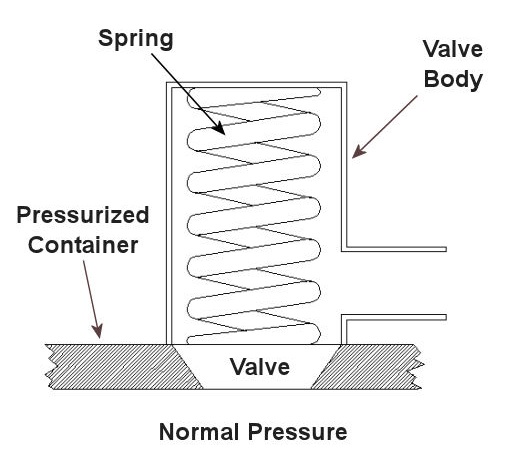
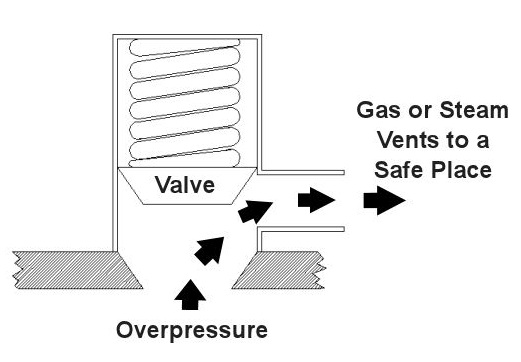
Last time we saw how something as seemingly harmless as a home water heater could become a dangerous missile if the pressure inside builds to the point where the tank ruptures. You can imagine what kind of explosive forces, steam, and chemicals would be unleashed into the surroundings if an industrial sized pressurized container failed due to overpressure. Let’s explore some other types of overpressure devices that are commonly used in industrial settings. One type of overpressure device is a safety valve. They are similar to a water heater relief valve, but they are generally used to relieve overpressure of gases and steam. How do they work? Basically, a safety valve is attached to the top of a pressurized container as shown in the cut away view in Figure 1 below. Figure 1 – A Basic Safety Valve In The Closed Position A powerful spring in the valve body is designed to force down on the valve and keep it closed if there is normal pressure inside the container. Once the pressure begins to rise to an unsafe level, it pushes up against the valve and overcomes the force of the spring. The valve opens, as shown in Figure 2 below, and the contents of the pressurized container are safely vented out to an area that is normally unoccupied by people. In case you’re wondering, safety valves are commonly used on pressurized storage tanks and boilers. Figure 2 – A Basic Safety Valve In The Open Position Another way to address the overpressure scenario is to employ a rupture disc. This is in fact a purposely constructed weak spot. It is intentionally built into a pressurized container and is designed so that it will fail when pressure starts to rise. In fact, this disc is designed to fail at a pressure point just below the pressure at which the container itself would fail. The disc is usually located within a vent pipe, which is in turn connected to the container. Should the disc rupture in an overpressure situation, the contents of the pressurized container will safely flow out of the vent pipe to a place normally unoccupied by people. The advantage of using a rupture disc is that they are made to safely release huge quantities of pressurized substances very quickly. The disadvantage in their usage is that they’re a one-time fix. That is, unlike relief or safety valves which may perform their function a multitude of times, a rupture disc is destroyed once it does its job. They are generally used in industrial settings where potential hazards are greater than at home, so once the rupture disc blows, the complete system generally undergoes a shut down so that the disc an be replaced before the pressurized container can be used again. Another option to pressure containment is the use of a fusible plug, usually constructed of a metal that will melt if the temperature within a pressurized container rises above a certain level. The metal plug melts, and excess pressure is vented through the aperture formed into a safe location. These are often used on locomotive boilers and compressed gas cylinders. Like rupture discs, fusible plugs are a one-time fix and must be replaced once they have done their job. Yet another option to pressure containment is to use a temperature limiting control. This category includes devices that monitor temperature and pressure within a pressurized container. If a dangerous situation should develop, the control system reacts, effectively reducing the pressure to prevent failure of the vessel. Automatic combustion control systems for boilers in electric utility power plants use temperature and pressure sensors to keep pressures within safe limits by regulating fuel and air input to the boiler. Next time we’ll cover the American Society of Mechanical Engineers (ASME) Boiler and Pressure Vessel Code (BPVC), which establishes rules governing the design, fabrication, testing, inspection, and repair of boilers and other pressurized containers. _____________________________________________ |
Nuclear Power, Is It The Answer?
Sunday, April 18th, 2010|
In weeks past we’ve explored wind energy and the possibility of it overtaking fossil fuel burning plants as our main source of power. This week we’ll discuss the next most viable option to do the job, that of nuclear power. Nuclear power, unlike fossil fuel plants, doesn’t combust fuel and therefore doesn’t contribute to air pollution. But unlike wind turbines, their electrical output is reliable, that is to say, we know, save for a major breakdown, that they will put out X-amount of power every day, regardless of weather conditions. As a matter of fact, according to the Nuclear Energy Institute, the 103 nuclear power plants in operation in the United States today are the most reliable and efficient producers of energy to our electric power grid. They account for about 20% of the power generated and produce a total capacity of 96.245 gigawatts, meaning, a whopping 96.245 billion watts. Nuclear energy is clean, reliable, and produces loads of power, so why not initiate a program to begin immediate replacement of our dirty fossil fueled plants? It’s time to take a closer look. Needless to say, large scale replacement of fossil fueled power plants with nuclear power plants would be a huge undertaking. You’ll remember from my previous blog postings that the US Department of Energy reports that 71.2% of our power is currently being produced by burning fossil fuels. All power plants, and especially nuclear power plants, are extremely expensive to build. Let’s look at an example. In 2007, Florida Power & Light informed the Florida Public Service Commission that the cost to build a new nuclear plant in south Florida would be approximately $8,000 per kilowatt-hour. How does this large sum affect the consumer in terms of real dollars? Well, let’s say you want to build a 3,000 megawatt (3,000 million watt) nuclear plant. This is enough capacity to provide power for about 2 million people in the US. When all is said and done, you’ll end up having to pay out $24 billion before you can start generating electricity. That looks like a lot of cash outlay for one plant, but what does it mean to each individual? If we do the math, a nuclear plant that is capable of supplying 2 million people with electricity will result in a cost of approximately $12,000 per person. Considering that, will investors, taxpayers, and consumers be willing to cover the losses that accrue when all existing fossil plants are closed and nuclear plants are erected to replace them? As with wind powered energy, cost is an enormous factor when considering the viability of nuclear power plants, but there is something way more profound to consider. Nuclear power plants produce radioactive waste. This waste remains radioactive, and therefore highly poisonous to the environment, for millions of years. That’s right, millions, not hundreds, not thousands, millions of years. The Nuclear Energy Information Service states that for each nuclear reactor that exists, 50 to 60 tons of high level radioactive waste is produced every year. So you’ve got all this waste as a byproduct of nuclear energy production, and, of course, there’s a lot of controversy surrounding its safe disposal. Not only does it lay around for millions of years, the costs of dealing with it are staggering. The US Department of Energy estimated in 2008 that it will cost around $96 billion to construct the Yucca Mountain nuclear waste repository in Nevada, which is basically a huge underground garbage dump for nuclear waste. And this amount of money will only keep it in operation for about 150 years. What happens after that? And if we build more nuclear plants in addition to those that currently exist, what will then be the cost of disposing of their waste? No one knows for sure, but they know it’s a mighty large sum, and certainly much too large for the ailing American economy to absorb. Now, Dr. Seuss, the guy that wrote The Cat in the Hat and other wonders, was an actual person, and he had a lot to say about things that didn’t involve gnarly looking creatures that go “BUMP!” in the night: “Sometimes the questions are complicated and the answers are simple.” Well, that’s sort of the case here. There are a lot of seemingly simple answers being posed to address our energy and environmental problems, but when you start asking pointed questions to delve deeply into the feasibility of those answers, things can get extremely complicated. We have seen through our present blog series that these answers inevitably lead to more questions and a multiplicity of other problems, and so far we haven’t seen an easy fix to our energy issues. But are we just making an issue where none exists? Are we making a mountain out of a mole hill? Next week we’ll explore a few more options that are being considered as alternative energy sources. Perhaps there is an easy answer to our power dilemma. _____________________________________________ |
Thermodynamics in Mechanical Engineering, Part IV, Stoichiometry
Sunday, December 27th, 2009|
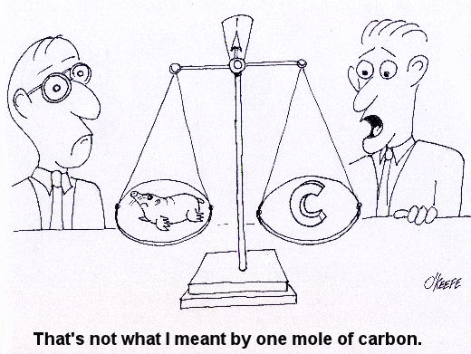
Last week we talked about an area of thermodynamics that concerns refrigeration cycles as presented through the example of an air conditioner. This week, we’ll learn about stoichiometry, which is concerned with the math behind chemical reactions, like those that take place during the burning of fuels. During the combustion process, heat energy is released from a fuel when the combustible elements in the fuel combine with oxygen. This is known as oxidation, or in common everyday language as burning. The most important thing to remember about oxidation is that it obeys the first law of thermodynamics. That is, mass cannot be created or destroyed. In a chemical reaction like combustion, particles of fuel and air are rearranged in space and then combine to form different substances. However, despite the rearranging, the mass that goes into the reaction must equal the mass that comes out. This conservation of mass is the basis of stoichiometry. For example, if pure carbon (represented by the chemical symbol “C”) is burned in pure oxygen (O2), you can represent the combustion process as: C + O2 → CO2 This is chemistry shorthand for representing how carbon and oxygen combine during burning to form carbon dioxide (CO2). The elements to the left of the arrow are known as “reactants” and the elements to the right are known as “products.” In stoichiometry, the mass of the reactants must equal the mass of the products. But, how do we quantify the mass of reactants and products? Now this is where it gets a little weird. To make use of our chemistry shorthand above, we have to consider something called moles. No, these aren’t the little furry creatures that tunnel under your lawn and eat your tulip bulbs. In stoichiometry a mole is considered to be 6.02×10²³ molecules of a substance. That is 602,000,000,000,000,000,000,000 molecules! Okay, so we have one heck of a lot of molecules in a mole. So, what does that have to do with figuring out how much mass we are dealing with in the combustion process? Well, in order to make moles work for us, we have to take into consideration the differing molecular weights of substances. Molecular weight is the number of grams (g) of mass that are contained within one mole of a substance, like the element carbon in our example above. To help make stoichiometry more workable, scientists created a table that provides the molecular weight of all known chemical elements. This table is known as the Periodic Table of Elements, or the “Periodic Table” for short. Now going back to our example above, if we know from the Periodic Table that carbon has a molecular weight of 12 g per mole and oxygen has a molecular weight of 16 g per mole, then how many grams of carbon dioxide do we get by burning carbon in pure oxygen? The combustion process can be represented by this equation: C + O2 → CO2 (12 g/mole) × (1mole of carbon) + (16 g/mole) × (2 moles of oxygen) = 44 g of carbon dioxide This is a fairly straightforward example of how stoichiometry works. In reality, things can get far more complicated. In a power plant for example, fuels like coal contain substances in addition to carbon, such as hydrogen and sulfur, and they, too, must be factored into the stoichiometric accounting system. To further complicate things, fuels are usually burned in air, rather than pure oxygen. Air, too, contains substances other than oxygen, including nitrogen, argon, and molecules of water. These other substances’ presence in fuel and air make the combustion process more challenging to account for, because they all get mixed together, and they can combine into all sorts of other substances. Despite these complicating factors, the first law of thermodynamics must be obeyed, so the balancing act is still the same: mass of the reactants must equal the mass of the products. Once mechanical engineers use stoichiometry to figure out what’s going in and coming out of the combustion process, they can then use the data provided by chemical analysis of the fuel to calculate the heat energy that is released. They can also calculate the air required for proper combustion. This helps them to design things capable of delivering enough fuel and air to meet the heat input requirements for a diversity of power cycles, from the engine in your car to the coal fired power plant supplying electricity for your home. Next week, we’ll talk about psychrometric analysis. No, this has nothing to do with psychiatry. Psychrometrics involves the analysis of gas and vapor mixtures like air and water. _________________________________________________________________ |
Thermodynamics In Mechanical Engineering, Part II, Power Cycles
Sunday, December 13th, 2009|
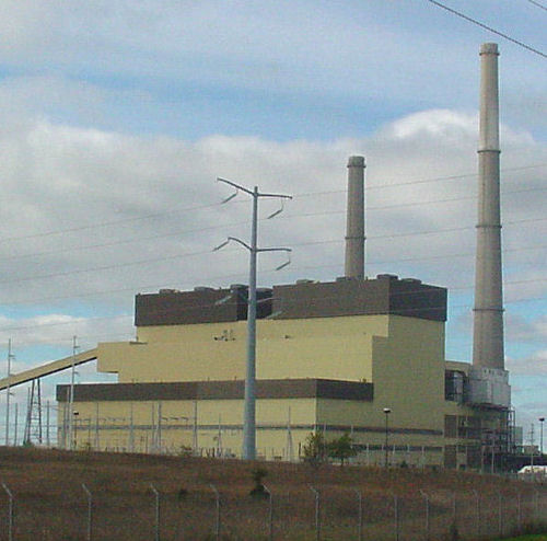
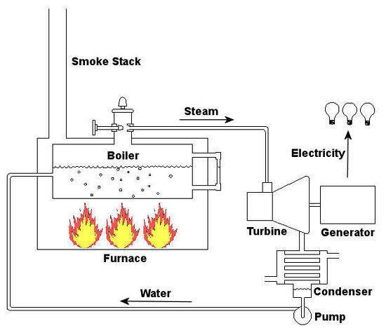
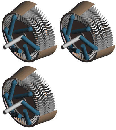
Last time we talked about some general concepts in an area of mechanical engineering known as thermodynamics. In this week’s article we’ll narrow our focus a bit to look at a part of thermodynamics that deals with power cycles. One mammoth example of a power cycle can be found in a coal-fired power plant. You can’t help but notice these plants with their massive buildings, mountains of coal, and tall smoke stacks. They’ve been getting a lot of negative press lately and are a central focus of the debate on global warming, but most people have no idea what’s going on inside of them. Let’s take a peek. Figure 1 – A Coal-Fired Power Plant A power plant has one basic function, to convert the chemical energy in coal into the electrical energy that we use in our modern lives, and it’s a power cycle that is at the heart of this conversion process. The most basic power cycle in this instance would include a boiler, steam turbine, condenser, and a pump (see Figure 2 below). Figure 2 – A Basic Power Cycle When the coal is burned in the power plant furnace, its chemical energy is turned into heat energy. This heat energy and the boiler are enclosed by the furnace so the boiler can more efficiently absorb the heat energy to make steam. A pipe carries the steam from the boiler to a steam turbine. Nozzles in the steam turbine convert the heat energy of the steam into kinetic energy, making the steam pick up speed as it leaves the nozzles. The fast moving steam transfers its kinetic energy to the turbine blades, causing the turbine to spin, much like a windmill (see Figure 3 below). Figure 3 – The Inner Workings of a Steam Turbine The spinning turbine is connected by a shaft to a generator. The turbine works to spin the generator and thus produces electricity. After the energy in the steam is used by the turbine, it goes to the condenser, whose job it is to convert the steam back into water. To accomplish this, the condenser uses cold water, say from a nearby lake or river, to cool the steam down until it converts from a gas back to a liquid, that is, water. This is why power plants are normally found adjacent to a body of water. After things are cooled down, the pump gets to work, pushing the condensed water back into the boiler where it is once again turned into steam. This power cycle keeps repeating itself as long as there is coal being burned in the furnace, the plant equipment is functioning properly, and electrical energy flows out of the power plant. Thermodynamics sets up an energy accounting system that enables mechanical engineers to design and analyze power cycles to make sure they are safe, reliable, efficient, and economical. When all is said and done, a properly designed power cycle transfers as much heat energy as possible from the burning coal on one end of the cycle to meet the requirements for electrical power on the other end of the cycle. As was mentioned in last week’s blog, nothing is 100% efficient. Next time we’ll learn about being cool. No, I’m not going to talk about the latest cell phone gadget or who’s connected on Facebook. We’ll be covering refrigeration cycles. _________________________________________________________________ |
