|
Last time we learned how Henry Cavendish used Christiaan Huygens’ work with pendulums to determine the value of g, the acceleration of gravity factor for Earth, to be 32.3 ft/sec2, or 9.8 m/sec2. From there Cavendish was able to go on and arrive at values for other factors in Isaac Newton’s gravity formula, namely G, the universal gravitational constant, and M, Earth’s mass. Today, we’ll discuss how Cavendish was able to calculate the Earth’s mass. Newton’s formula for gravity, once again, is: M = (g × R2) ÷ G where M stands for the mass of the heavenly body being quantified. For our case today M will represent the mass of Earth, which was originally quantified in slugs, a British unit of measurement. Today the measurement unit of choice in most parts of the world is the kilogram, which is the metric equivalent of a slug. With regard to the other variables in Newton’s gravity formula, namely, R and G, their values had previously been determined. Eratosthenes’ measurement of shadows cast by the sun on Earth’s surface had revealed Earth’s radius, R, to be 6,371 kilometers, or 6,371,000 meters. And Cavendish’s experiments led him to conclude that the universal gravitational constant, G, was 6.67 × 10⁻¹¹ cubic meters per kilogram-second squared. Plugging these values into Newton’s equation, we calculate Earth’s mass to be: M = ((9.8 m/sec2) × (6,371,000 m)2) ÷ (6.67 × 10⁻¹¹ m3/kg-sec2) M = 5.96 × 1024 kilograms Incidentally, 5.96 × 1024 is scientific notation, or mathematical shorthand, for the number 5,960,000,000,000,000,000,000,000. That’s a whole lot of zeros! Calculating the mass of Earth was an impressive accomplishment. Now that its value was known, scientists would be able to calculate the mass and acceleration of gravity for any heavenly body in the universe. We’ll see how that’s done next time.
_______________________________________
|
Posts Tagged ‘mechanical engineering expert witness’
What is Earth’s Mass?
Friday, November 7th, 2014The Gear Train Tradeoff
Tuesday, August 5th, 2014|
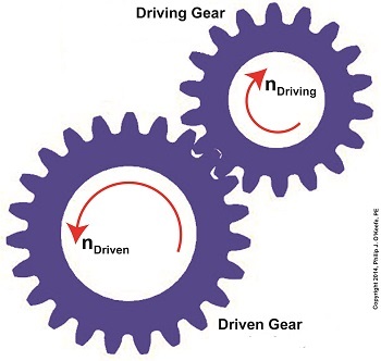
We’ve learned several methods to increase the torque of an electric motor through our series of articles on gear trains. One way is to attach a gear train to the motor’s shaft, a relatively simple thing to do. Today we’ll begin our exploration into how this method involves a tradeoff. It comes at the cost of speed. We’ll begin our examination of the tradeoff at play by linking together key elements learned through past blogs on the subject of gear trains. We’ll revisit those lessons through flashbacks. The first flashback we’ll make is to a blog entitled, Gear Ratio Formulas. There we learned that within a simple gear train consisting of two gears, the type most commonly employed to manipulate a motor’s torque, the ratio between the two gears, R, is relative to the ratio of their gear teeth, N. N is determined by the number of teeth each gear has in combination with the speeds, n, that each gear is going: R = NDriven ÷ NDriving = nDriving ÷ nDriven (1) The second flashback we’ll make is to a blog entitled, The Methodology Behind Gear Train Torque Conversions, in which we learned that the ratio of the torque, T, that exists between the gears is relative to the ratio of their respective pitch diameters, D: TDriving ÷ TDriven = DDriving ÷ DDriven (2) The tradeoff we’ve been alluding to comes in when gear speed, nDriven, represented in equation (1), is decreased, which results in an increase to TDriven in equation (2). But in order to see this we’ve got to somehow link the two equations together. In their present form there’s no common link between them. Or is there? There actually is an indirect link between the two equations, which comes by way of the torque equation presented in another past blog. The third flashback we’ll make is to the blog discussing that subject, which is entitled, The Relationship Between Torque and Horsepower. Using facts presented in that blog, the torque equations for our two gears become: TDriving = [HPDriving ÷ nDriving] × 63,025 (3) TDriven = [HPDriven ÷ nDriven] × 63,025 (4) Where’s the link between equations (1) and (2)? To answer that question we must reference a physics law known as The Law of Conservation of Energy . It states that the energy flowing from one gear to another within a gear train remains constant. Energy equates to horsepower, HP, in equations (3) and (4). So if the horsepower flowing through the gears is equal, our working equation becomes: HPDriving = HPDriven (5) Next time we’ll see how equation (5) is key to linking together equations (1) and (2) by way of equations (3) and (4). In so doing we’ll disclose the tradeoff to using gear trains. _______________________________________
|
How to Increase Gear Train Torque
Thursday, July 10th, 2014|
Last week we worked with a gear train equation and found that the gears under consideration were not sized properly to run a lathe. Today we’ll increase the gear train torque and solve that problem. How do we manipulate things to obtain the 275 inch pounds of torque required to drive the lathe? Last week we tried using a driven gear with a diameter of 8 inches and found that to be insufficient in size. So today the first thing we’ll try is a bigger driven gear, one with a pitch diameter of 8.5 inches. That’s 0.5 inches larger in diameter than the gear used in last week’s equation, and this just so happens to be the next size up in the gear manufacturer’s catalog. As we did last week, we’ll begin our calculations with the torque ratio equation: T1 ÷ T2 = D1 ÷ D2 We’ll use the same values as last week for T1, and D1, 200 inch pounds and 3 inches respectively, but we’ll increase the new value for D2, the driven gear pitch radius, to 4.25 inches (the new pitch diameter divided by two). Inserting these values into the torque equation, the only variable remaining without a value is torque T2. Let’s determine that value now by using algebra to rearrange terms. (200 inch pounds) ÷ T2 = (3 inches) ÷ (4.25 inches) (200 inch pounds) ÷ T2 = 0.70 T2 = (200 inch pounds) ÷ (0.70) = 283.33 inch pounds The value of T2 is found to be 283.33 inch pounds, which meets the torque requirement required to run the lathe. We were able to arrive at this torque by simply increasing the size of the driven gear relative to the size of the driving gear. In the world of Newtonian physics, this is a rather straightforward arrangement. It all boils down to this simple dynamic: When the motor’s force is acting upon a wider gear, the force is located a longer distance from the center of the driving gear shaft, which results in more torque on the shaft. As borne out by the example provided today, the larger the driven gear is in comparison to the driving gear, the more the gear train amplifies the torque that’s delivered by the motor. The principle at play here is exactly the same as that presented in a previous blog article where, for a given force exerted upon a wrench, torque was increased by simply increasing the length of the wrench handle. Some of you may be wondering why we didn’t just use a bigger, more powerful motor to begin with, thereby eliminating the need for a gear train and all the calculations we’ve been running? We’ll see why that’s not always possible or practical next time. _______________________________________
|
Determining Torque Within a Gear Train
Monday, June 30th, 2014|
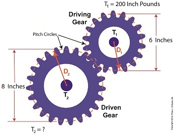
Last time we set up an example where an electric motor is connected to a lathe via a gear train. Today we’ll take the numerical values present on that gear train and plug them into the torque ratio equation we’ve been working with for the past few blogs. In the illustration below the electric motor exerts 200 inch pounds of torque upon the driving gear. The driving gear pitch circle diameter is 6 inches, while the driven gear pitch circle diameter is 8 inches. It’s been determined through previous lab testing that the lathe we’ll be using requires at least 275 inch pounds of torque to be exerted upon the driven gear shaft in order to operate properly. Will the gear train shown below meet this requirement? First, a review of the torque ratio equation: T1 ÷ T2 = D1 ÷ D2 Now we’ll crunch numbers. T1 is equal to 200 inch pounds, D1 is equal to 3 inches (pitch radius equals pitch diameter divided by two), and D2 is equal to 4 inches. This gives us: (200 inch pounds) ÷ T2 = (3 inches) ÷ (4 inches) T2 = (200 inch pounds) ÷ (0.75) = 266.67 inch pounds So, does the gear train as presented here supply enough torque to power the lathe properly? No, it does not. It provides only 266.67 inch pounds, not the 275 inch pounds of torque required. Next time we’ll see how to manipulate gear sizes within a gear train in order to meet a given torque requirement. _______________________________________
|
Gear Trains Are Torque Converters and Why That’s Important
Friday, June 13th, 2014|
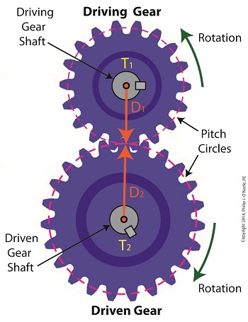
Today we’ll analyze the relationship between the sizes of the gears within a gear train, as well as their torques, and get an understanding of how gear trains act as torque converters. Last time we developed a single torque equation for a simple gear train: T1 ÷ D1 = T2 ÷ D2 (1) where T1 and T2 are the driving and driven gear torques, and D1 and D2 are the driving and driven gear pitch circle radii. The first thing to be done in order to arrive at a torque conversion analysis is group together like terms in equation (1) so that we end up with terms relating to torque on one side of the equation and terms relating to gear size on the other. We’ll use algebra to divide both sides of the equation by T2 , then multiply both sides by D1. After doing so we get, T1 ÷ T2 = D1 ÷ D2 (2) In equation (2), T1 ÷ T2 is a torque ratio. Ratio means we’re dividing one of the torques by the other. Likewise, D1 ÷ D2 is a gear pitch radius ratio, that is to say, it’s the ratio of one gear’s physical size relative to the physical size of the other. What equation (2) tells us is that the individual gears on the gear train will produce torque values which are dependent upon the physical sizes of the two gears with respect to one another. So what’s the practical significance of this? When gear trains are used in industrial applications, they always act as torque converters. One such example would be when a low-torque-producing electric motor is used to power a steel cutting lathe. If the motor isn’t tough enough to power the lathe, it itself won’t be modified, but the torque it produces will be. This modification is accomplished by converting the motor’s low torque value, T1, to a higher torque value, T2 , and it’s equation (2) that’s used to do it. Next time we’ll delve deeper into the methodology behind gear train torque conversions. _______________________________________
|
Manipulating theTorque Formula
Wednesday, April 23rd, 2014|
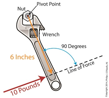
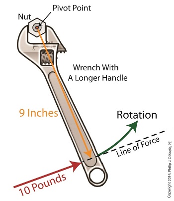
Last time we introduced the simplified formula for torque: Torque = Distance × Force Today we’ll manipulate it by way of our wrench and nut example to get the torque that we need to loosen a tight nut. By inserting the numerical values of our illustration into the torque formula, it becomes: Torque = 6 inches × 10 pounds = 60 inch-pounds Inch-pounds may be terminology you’re unfamiliar with, but this notation arises from the fact that torque values are always represented by units of distance and force separated by a hyphen, in our case inch-pounds. This just means that distance and force were multiplied together to calculate torque. In order to manipulate the value for torque all that needs to be done is change either or both numerical values for Distance and Force. Increasing either or both factors produces higher torque, decreasing them less torque. Why manipulate torque? To provide us with a mechanical advantage. Suppose we have a rusted nut that we’re trying to move with a wrench that has a 6 inch handle, and the 10 pounds of force employed by the muscles in our arm just won’t budge it. Put another way, 60 inch-pounds of torque is insufficient to rotate the nut. It’s clear we must increase torque to get things going. Let’s do so by increasing either of the vector magnitudes. First we’ll try increasing the magnitude of the force vector. Instead of simply pushing hard on the wrench handle with our arm, let’s say we push extra hard. The average man can do a bicep curl of between 30 to 40 pounds, but we haven’t been going to the gym lately and we’re really out of shape. So try as we will, we just can’t muster up the bicep strength to apply more than 10 pounds of force to the wrench handle. It’s clear that this approach to increasing torque upon the nut isn’t going to work. The other way to increase torque is to increase the length of the distance vector. We’ll need a wrench with a longer handle, say 9 inches. By using a wrench with a longer handle we have increased the magnitude of the distance vector from 6 to 9 inches. The torque formula becomes: Torque = 9 inches × 10 pounds = 90 inch-pounds Eureka! The longer handle has provided us with the mechanical advantage needed to increase torque to 90 inch-pounds, thereby overcoming our muscular shortcomings and breaking the nut free. In summary, since torque is the product of the magnitudes of the distance and force vectors, we can increase torque by either increasing the magnitude of the force vector, or as in our example, by increasing the magnitude of the distance vector. Next time we’ll see how to apply the principles of torque to a real world situation involving gear trains in which we need to obtain a mechanical advantage. _______________________________________ |
Achieving Mechanical Advantage Through Torque
Wednesday, March 19th, 2014|
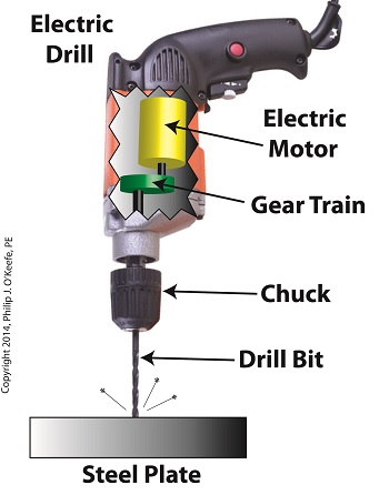
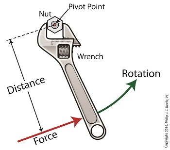
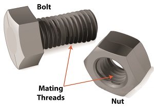
Last time we saw how gear train ratios allow us to change the speed of the driven gear relative to the driving gear. Today we’ll extend this concept further and see how gear trains are used to amplify the mechanical power output of small motors and in so doing create a mechanical advantage, an advantage made possible through the physics of torque. Below is an ordinary electric drill. Let’s see what’s inside its shell. There’s a whole lot of mechanical advantage at work here, giving the drill’s small motor the ability to perform big jobs. A motor and gear train are housed within the drill itself. The motor shaft is coupled to the chuck shaft via the gear train, and by extension, the drill bit. A chuck holds the drill bit in place. It’s the drill’s gear train that provides the small motor with the mechanical advantage necessary for this hand-held power tool to perform the big job of cutting through a thick steel plate. If the gear train and its properly engineered gear ratio weren’t in place and the chuck’s shaft was connected directly to the motor shaft, the motor would be overwhelmed and would stall or become damaged. Either way, the work won’t get done. To understand how operations like these can be performed, we must first familiarize ourselves with the physics concept of torque. Torque allows us to analyze the rotational forces acting upon rotating objects, such as gears in a gear train and wrenches on nuts and bolts. Manipulating torque allows us to achieve a physical advantage when rotating objects around a pivot point. Let’s illustrate this by using a wrench to turn a nut. The nut is fastened to the bolt with threads, interconnecting spiral grooves formed on both the inside of the nut and the outside of the bolt. A wrench is used to loosen and tighten the nut by rotating it on its mating threads. The nut itself rotates about a pivot point which lies at its center. When you use your arm to manipulate the wrench you apply force, a force which is transmitted at a distance from the pivot point. This in turn creates a torque on the nut. In other words, torque is a function of the force acting upon the handle relative to its distance from the pivot point at the center of the nut. Torque can be increased by changing one or both of its acting factors, force and distance. We’ll see how next time when we examine the formula for torque and manipulate it so that a weak arm can loosen even the tightest nut. _______________________________________ |
Gear Terminology
Sunday, January 5th, 2014|
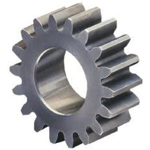
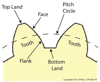
Last time we reviewed the ancient origins of gears and saw how they’ve been around a lot longer than most people realize. Now let’s familiarize ourselves with the terminology of modern gears by taking a look at the most basic and commonly used gear construction, the spur gear. A spur gear is shown below, so named due to its resemblance to spurs commonly found attached to horse riding boots. At their most basic gears are wheels containing many projections which resemble teeth. These teeth are equally spaced around the wheel’s circumference and are designed to mesh, or fit together, with the teeth of other like gears. Looking more closely at the teeth of a modern spur gear, we see they have a rather complex and peculiar curved shape, along with their own terminology. There’s a pitch circle that intersects each gear tooth between the root of the tooth, or bottom land, and the tip of the tooth, or top land. Above the pitch circle each tooth side bears a face. Below the pitch circle and under each face is a flank. Spur gear teeth don’t necessarily have to have this shape. All that’s required is that the teeth fit together in such a way so as to permit fluid interaction between them as they rotate. As a matter of fact, some primitive gears consisted of wooden wheels with teeth made of wooden pegs. These pegs were inserted into evenly spaced holes which were drilled around the circumference of the wheel. The wooden pegs of each wheel would mesh with one another, and when one gear wheel was caused to rotate, its pegs would press against the pegs of the other gear, making it rotate along with it. So if simple pegs worked well enough, then why are modern gear teeth so specifically shaped? We’ll see why next time when we join gears together to form a gear train. ________________________________________ |
Mechanical Engineering, Focus on Statics
Sunday, October 18th, 2009|
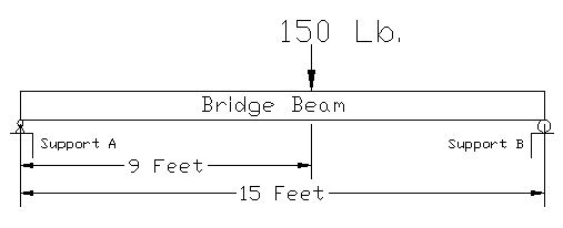
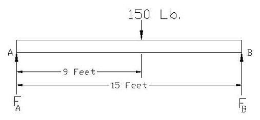
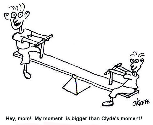
As I stated in my last blog post, Statics is the study of how forces are transmitted to and throughout stationary objects. Let’s learn a little bit about how statics is used by mechanical engineers to solve problems. Consider a perfectly rigid bridge beam sitting on two supports (see Figure 1). Now suppose you decide to stand on it. The weight of your body would push down on the beam, creating a system of forces that act upon the beam. If the beam stays on its supports and doesn’t move (it remains static), then the forces are said to be in “equilibrium.” In other words, since the beam doesn’t move when you stand on it, the sum of all the forces acting upon it are zero. Figure 1 So what, you say? Well, this concept of forces in equilibrium helps mechanical engineers analyze external and internal forces acting on stationary objects that have importance to us in real life, like bridges, machines, traffic signal masts, etc. This analysis is used to calculate the magnitudes of all the forces acting on these objects so they can design parts of the objects to be strong enough not to break apart. Think about that next time you get ready to cross a bridge in your car. To show how this works, consider the bridge beam scenario I discussed above. Suppose you weigh 150 pounds and you stand nine feet from the left end of the bridge beam (see Figure 2). Your weight will exert a downward force of 150 pounds upon the beam (let’s ignore the weight of the beam in this case). The weight of your body creates reaction forces on the beam at Support A and Support B. To consider these reaction forces, the mechanical engineer would draw what is called a “free body diagram” (see Figure 3). Figure 2 Figure 3 The reaction forces (FA and FB) at the supports A and B push up on the bottom of the beam. If the beam remains static, then the sum of the reaction forces will equal the 150 pound weight force from your body. That is, the reaction forces cancel out the 150 pound force if the beam doesn’t move and they are said to be in equilibrium. But in our example above, you’re not standing in the exact center of the beam, hence the two reaction forces are not going to be equal. More of your body weight force is bearing down on Support B and less on Support A. So how do you determine the values of the reaction forces in a situation like this? You consider “moments.” A moment is mechanical engineering lingo for a force multiplied by a distance. Moments want to rotate objects. This is an important concept in statics because if an object doesn’t move, it certainly won’t rotate, so the sum of all the moments acting on the object are zero. So, in the case of our bridge beam, the sum of the moments acting on Support A would be zero, or mathematically speaking: Sum MA = [(FA) x (0 Feet)] – [(150 Lb.) x (9 Feet)] + [(FB) x (15 Feet)] = 0 Using algebra, you can find the value for the reaction force at Support B: [0] – [(150 Lb.) x (9 Feet)] + [(FB) x (15 Feet)] = 0 [(FB) x (15 Feet)] = [(150 Lb.) x (9 Feet)] FB = 90 Lb. So what about the reaction force at Support A? If you remember, I said that if the bridge beam remains static, then the sum of all the forces acting on it will be zero. Knowing that, you can use algebra to solve for the reaction force at Support A: FA -150 Lb + FB = 0
FA = 150 Lb. – 90 Lb. = 60 Lb. So that is the basic concept of statics. Remember, in statics, nothing moves, so mechanical engineers use that to their advantage when they analyze forces acting on objects. Our next topic will be: Dynamics, the study of the effects of velocity and acceleration and resulting forces and the energy of moving objects. Last week’s Riddle: Everyone knows us to be racing by when they look at a clock, but mechanical engineers also know us to add up to zero when they look at a fixed structure. What are we? Answer: Moments _________________________________________________________________ |
