Posts Tagged ‘electric motor’
Friday, April 21st, 2017
|
Last time we saw how pulley diameter governs speed in engineering scenarios which make use of a belt and pulley system. Today we’ll see how this phenomenon is defined mathematically through application of the Pulley Speed Ratio Formula, which enables precise pulley diameters to be calculated to achieve specific rotational speeds. Today we’ll apply this Formula to a scenario involving a building’s ventilating system.
The Pulley Speed Ratio Formula is,
D1 × N1 = D2 × N2 (1)
where, D1 is the diameter of the driving pulley and D2 the diameter of the driven pulley.
A Pulley Speed Ratio Formula Application
The pulleys’ rotational speeds are represented by N1 and N2, and are measured in revolutions per minute (RPM).
Now, let’s apply Equation (1) to an example in which a blower must deliver a specific air flow to a building’s ventilating system. This is accomplished by manipulating the ratios between the driven pulley’s diameter, D2, with respect to the driving pulley’s diameter, D1. If you’ll recall from our discussion last time, when both the driving and driven pulleys have the same diameter, the entire assembly moves at the same speed, and this would be bad for our scenario.
An electric motor and blower impeller moving at the same speed is problematic because electric motors are designed to spin at much faster speeds than typical blower impellers in order to produce desired air flow. If their pulleys’ diameters were the same size, it would result in an improperly working ventilating system in which air passes through the furnace heat exchanger and air conditioner cooling coils far too quickly to do an efficient job of heating or cooling.
To bear this out, let’s suppose we have an electric motor turning at a fixed speed of 3600 RPM and a belt-driven blower with an impeller that must turn at 1500 RPM to deliver the required air flow according to the blower manufacturer’s data sheet. The motor shaft is fitted with a pulley 3 inches in diameter. What pulley diameter do we need for the blower to turn at the manufacturer’s required 1500 RPM?
In this example known variables are D1 = 3 inches, N1 = 3600 RPM, and N2 = 1500 RPM. The diameter D2 is unknown. Inserting the known values into equation (1), we can solve for D2,
(3 inches) × (3600 RPM) = D2 × (1500 RPM) (2)
Simplified, this becomes,
D2 = 7.2 inches (3)
Next time we’ll see how friction affects our scenario.
Copyright 2017 – Philip J. O’Keefe, PE
Engineering Expert Witness Blog
____________________________________ |
Tags: belt, blower, blower impeller, cooling coils, drive belt, driven pulley, driving pulley, electric motor, engineering, heat exchanger, mechanical power transmission, pulley, pulley speed, Pulley Speed Ratio Formula, RPM, ventilating system
Posted in Engineering and Science, Expert Witness, Forensic Engineering, Innovation and Intellectual Property, Personal Injury, Product Liability | Comments Off on A Pulley Speed Ratio Formula Application
Saturday, April 8th, 2017
|
Soon after the first pulleys were used with belts to transmit mechanical power, engineers such as Leonhard Euler and Johann Albert Eytelwein discovered that the diameter of the pulleys used determined the speed at which they rotated. This allowed for a greater diversity in mechanical applications. We’ll set up an examination of this phenomenon today.
Last time we introduced this basic mechanical power transmission system consisting of a driving pulley, a driven pulley, and a belt, which we’ll call Situation A.
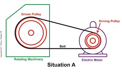
A Driven Pulley’s Larger Diameter Determines a Slower Speed
In this situation, the rotating machinery’s driven pulley diameter is larger than the electric motor’s driving pulley diameter. The result is the driven pulley turns at a slower speed than the driving pulley.
Now let’s say we need to speed the rotating machinery up so it produces more widgets per hour. In that case we’d make the driven pulley smaller, as shown in Situation B.
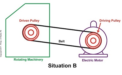
A Driven Pulley’s Smaller Diameter Determines a Faster Speed
With the smaller diameter driven pulley, the rotating machinery will operate faster than it did in Situation A.
Next week we’ll introduce the Pulley Speed Ratio Formula, which mathematically defines this phenomenon.
Copyright 2017 – Philip J. O’Keefe, PE
Engineering Expert Witness Blog
____________________________________ |
Tags: belt, driven pulley, driving pulley, electric motor, engineering, Johann Albert Eytelwein, Leonhard Euler, pulley diameter, Pulley Speed Ratio Formula, rotating machinery, rotational speed
Posted in Engineering and Science, Expert Witness, Forensic Engineering, Innovation and Intellectual Property, Personal Injury, Product Liability | Comments Off on Pulley Diameter Determines Speed
Friday, March 31st, 2017
|
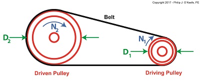
Last time we introduced two historical legends in the field of engineering who pioneered the science of mechanical power transmission using belts and pulleys, Leonhard Euler and Johann Albert Eytelwein. Today we’ll build a foundation for understanding their famous Euler-Eytelwein Formula through our example of a simple mechanical power transmission system consisting of two pulleys and a belt, and in so doing demonstrate the difference between driven and driving pulleys.
Our example of a basic mechanical power transmission system consists of two pulleys connected by a drive belt. The driving pulley is attached to a source of mechanical power, for example, the shaft of an electric motor. The driven pulley, which is attached to the shaft of a piece of rotating machinery, receives the mechanical power from the electric motor so the machinery can perform its function.
The Difference Between Driven and Driving Pulleys
Next time we’ll see how driven pulleys can be made to spin at different speeds from the driving pulley, enabling different modes of operation in mechanical devices.
Copyright 2017 – Philip J. O’Keefe, PE
Engineering Expert Witness Blog
____________________________________ |
Tags: belt, driven pulley, driving pulley, electric motor, engineering, Euler, Euler-Eytelwein Formula, Eytelwein, mechanical power, mechanical power transmission, pulley, pulley speed, rotating machinery
Posted in Engineering and Science, Expert Witness, Forensic Engineering, Innovation and Intellectual Property, Personal Injury, Product Liability | Comments Off on The Difference Between Driven and Driving Pulleys
Friday, August 15th, 2014
|
Hold onto your hats, we’re going to deal with a lot of equations today!
Last time we used flashbacks to previous blogs in this series to revisit key equations in our ongoing discussion of gear trains and torque. We also introduced The Law of Conservation of Energy in conjunction with five equations that together demonstrate how when increasing torque by use of a simple gear train, we do so at the cost of speed.
Those five equations are:
| R = NDriven ÷ NDriving = nDriving ÷ nDriven |
(1) |
|
|
| TDriving ÷ TDriven = DDriving ÷ DDriven |
(2) |
|
|
| TDriving = [HPDriving ÷ nDriving] × 63,025 |
(3) |
|
|
| TDriven = [HPDriven ÷ nDriven] × 63,025 |
(4) |
|
|
| HPDriving = HPDriven |
(5) |
where, R is the gear ratio, N the number of gear teeth, n the gear’s rotational speed, T the torque, D the gear pitch radius, and HP is the horsepower transmitted by the gears.

As we work the equations, keep in mind that our ultimate objective is to find a way to link together (1) and (2), the equations dealing with gear torque and speed. Once we accomplish this we’ll see how increased torque is obtained at the cost of speed. But because there are no common terms between equations (1) and (2), our first step is to develop one.
Developing a link between equations (1) and (2) is a process that begins with combining equations (2), (3), and (4).
| TDriving ÷ TDriven = DDriving ÷ DDriven |
(2) |
|
|
| TDriving = [HPDriving ÷ nDriving] × 63,025 |
(3) |
|
|
| TDriven = [HPDriven ÷ nDriven] × 63,025 |
(4) |
The common terms in these three equations are TDriving and TDriven, so we’ll manipulate things in order to group them together. We’ll substitute equation (3) for the TDriving term in equation (2), and substitute equation (4) for the TDriven term in equation (2). We are now able to link all three equations to get:
{[HPDriving ÷ nDriving] × 63,025} ÷ {[HPDriven ÷ nDriven] × 63,025}
= DDriving ÷ DDriven (6)
Now let’s go a step further to simplify equation (6). From equation (5) we know that the driving and driven gear horsepowers are equal. So, in equation (6), the HPDriving and HPDriven cancel out, along with the two 63,025 terms, allowing us to arrive at equation (7):
{[HPDriving ÷ nDriving] × 63,025} ÷ {[HPDriven ÷ nDriven] × 63,025}
= DDriving ÷ DDriven
| nDriven ÷ nDriving = DDriving ÷ DDriven |
(7) |
Next week we’ll use equation (7) to link together R, N, n, of equation (1) with D and T of equation (2) and in so doing disclose mathematically the tradeoff between torque and speed, then apply our findings to an example.
_______________________________________
|
Tags: driven gear, driving gear, electric motor, engineering blog, engineering expert witness, forensic engineer, gear equations, gear expert, gear formula, gear ratio, gear speed, gear train, gears, horsepower, law of conservation of energy, mechanical engineer expert witness, number of teeth, pitch diameter, torque
Posted in Engineering and Science, Expert Witness, Forensic Engineering, Innovation and Intellectual Property, Personal Injury, Product Liability | Comments Off on Determining the Gear Train Tradeoff of Torque vs. Speed, Part One
Monday, July 28th, 2014
|
Last time we learned that we can get more torque out of a motor by using one of two methods. In the first method we attach a gear train to the motor, then try different gear sizes until we arrive at the desired torque for the application. In the second method we eliminate the gear train altogether and simply use a higher horsepower motor to give us the torque we need.
Today we’ll explore the second method. We’ll use the equation presented in our last blog to determine torque, T, relative to a motor’s horsepower, HP, when the motor operates at a speed, n:
T = [HP ÷ n] × 63,025
In earlier blogs in this series we employed a gear train attached to an electric motor to power a lathe. It provided an insufficient 200 inch pounds of torque when 275 is required. Let’s use the equation and a little algebra to see how much horsepower this motor develops if it turns at a speed of 1750 RPM, a common speed for alternating current (AC) motors:
200 inch pounds = [HP ÷ 1750 RPM] × 63,025
200 = HP × 36.01
HP = 200 ÷ 36.01 = 5.55 horsepower
For the purpose of our example today, let’s say we’ve nonsensically decided not to use a gear train, leaving us with no choice but to replace the underpowered motor with a more powerful one. So let’s see what size motor we’ll need to provide us with the required horsepower of 275 inch pounds.

Using the torque equation and plugging in numbers already provided our equation becomes:
275 inch pounds = [HP ÷1750 RPM] × 63,025
275 = HP × 36.01
HP = 275 ÷ 36.01 = 7.64 horsepower
This tells us that we need to replace the 5.55 horsepower motor with a 7.65 horsepower motor.
As you might have guessed, the higher the motor’s horsepower, the larger that motor’s size and weight — if you’re not using a gear train, that is. Bigger, bulkier motors cost more to purchase and operate and also take up more space, which often makes them impractical to use.
All this translates to the reality that sometimes it just makes more sense to use a gear train to provide more torque. It’s a lot easier and cheaper to attach a gear train to a motor and manipulate its gear sizes to arrive at desired torque than it is to buy a bigger motor.
You may have deduced by now that it’s relatively easy to get more torque. Almost too easy. Next time we’ll see how increased torque comes at another type of cost, the cost of speed.
_______________________________________
|
Tags: electric motor, engineering expert witness, forensic engineer, gear sizes, gear train, horsepower, mechanical engineer, motor, motor speed, torque, torque equation
Posted in Engineering and Science, Expert Witness, Forensic Engineering, Innovation and Intellectual Property, Personal Injury, Product Liability | Comments Off on Equations Used to Manipulate Torque Relative to Horsepower
Tuesday, July 15th, 2014
| We’ve been discussing gear trains for some time now, and last time we posed the question: Why even bother using a gear train and performing complex computations to arrive at a desired torque for an application? Why not just use a bigger motor to start with? Today we’ll see why.
First, we must acknowledge that sometimes higher torque is achieved by simply using a more powerful motor. But sometimes this isn’t possible or practical.
To begin our discussion, we must first understand how torque is related to motor power, the amount of mechanical work a motor can perform. Torque is in fact a function of how much mechanical power a motor produces. In the United States motor power is typically measured in units of horsepower.
The following equation illustrates the relationship between torque, horsepower, and motor speed:
T = [HP ÷ n] × 63,025
where T is the motor shaft’s torque in units of inch-pounds, HP is the motor’s horsepower, and n is the speed of the motor shaft in revolutions per minute (RPM). The number 63,025 in the equation is a constant used to convert the units of horsepower and RPM into units of torque (inch pounds). This equation applies to all sources of mechanical power. Its versatility enables design engineers to easily determine if a mechanical power source can deliver the torque required to drive a particular piece of machinery.
The torque equation above tells us that in order to get a higher torque T for a given speed n, you’ll have to get a motor with a higher HP. Put another way, if your speed remains constant and you use a motor with higher horsepower, you’ll get more torque for your application simply by increasing the horsepower.
Next time we’ll plug numbers into our equation and see how it all works.
_______________________________________
|
Tags: electric motor, engineering expert witness, forensic engineer, gear train, horsepower, machinery, mechanical power, motor shaft, motor shaft torque, motor speed, torque
Posted in Engineering and Science, Expert Witness, Forensic Engineering, Innovation and Intellectual Property, Personal Injury, Product Liability, Professional Malpractice | Comments Off on The Relationship Between Torque and Horsepower
Thursday, July 10th, 2014
|
Last week we worked with a gear train equation and found that the gears under consideration were not sized properly to run a lathe. Today we’ll increase the gear train torque and solve that problem.
How do we manipulate things to obtain the 275 inch pounds of torque required to drive the lathe? Last week we tried using a driven gear with a diameter of 8 inches and found that to be insufficient in size. So today the first thing we’ll try is a bigger driven gear, one with a pitch diameter of 8.5 inches. That’s 0.5 inches larger in diameter than the gear used in last week’s equation, and this just so happens to be the next size up in the gear manufacturer’s catalog.
As we did last week, we’ll begin our calculations with the torque ratio equation:
T1 ÷ T2 = D1 ÷ D2
We’ll use the same values as last week for T1, and D1, 200 inch pounds and 3 inches respectively, but we’ll increase the new value for D2, the driven gear pitch radius, to 4.25 inches (the new pitch diameter divided by two).
Inserting these values into the torque equation, the only variable remaining without a value is torque T2. Let’s determine that value now by using algebra to rearrange terms.
(200 inch pounds) ÷ T2 = (3 inches) ÷ (4.25 inches)
(200 inch pounds) ÷ T2 = 0.70
T2 = (200 inch pounds) ÷ (0.70) = 283.33 inch pounds
The value of T2 is found to be 283.33 inch pounds, which meets the torque requirement required to run the lathe. We were able to arrive at this torque by simply increasing the size of the driven gear relative to the size of the driving gear.
In the world of Newtonian physics, this is a rather straightforward arrangement. It all boils down to this simple dynamic: When the motor’s force is acting upon a wider gear, the force is located a longer distance from the center of the driving gear shaft, which results in more torque on the shaft.
As borne out by the example provided today, the larger the driven gear is in comparison to the driving gear, the more the gear train amplifies the torque that’s delivered by the motor. The principle at play here is exactly the same as that presented in a previous blog article where, for a given force exerted upon a wrench, torque was increased by simply increasing the length of the wrench handle.
Some of you may be wondering why we didn’t just use a bigger, more powerful motor to begin with, thereby eliminating the need for a gear train and all the calculations we’ve been running? We’ll see why that’s not always possible or practical next time.
_______________________________________
|
Tags: driven gear, driving gear, electric motor, engine lathe, forensic engineer, gear diameter, gear failure, gear pitch, gear shaft, gear train, gear train design, gears, increasing torque, lathe, mechanical engineering expert witness, motor force, pitch diameter, torque, torque converter, wrench
Posted in Engineering and Science, Expert Witness, Forensic Engineering, Innovation and Intellectual Property, Personal Injury, Product Liability | Comments Off on How to Increase Gear Train Torque
Monday, June 30th, 2014
|
Last time we set up an example where an electric motor is connected to a lathe via a gear train. Today we’ll take the numerical values present on that gear train and plug them into the torque ratio equation we’ve been working with for the past few blogs.
In the illustration below the electric motor exerts 200 inch pounds of torque upon the driving gear. The driving gear pitch circle diameter is 6 inches, while the driven gear pitch circle diameter is 8 inches. It’s been determined through previous lab testing that the lathe we’ll be using requires at least 275 inch pounds of torque to be exerted upon the driven gear shaft in order to operate properly. Will the gear train shown below meet this requirement?

First, a review of the torque ratio equation:
T1 ÷ T2 = D1 ÷ D2
Now we’ll crunch numbers. T1 is equal to 200 inch pounds, D1 is equal to 3 inches (pitch radius equals pitch diameter divided by two), and D2 is equal to 4 inches. This gives us:
(200 inch pounds) ÷ T2 = (3 inches) ÷ (4 inches)
T2 = (200 inch pounds) ÷ (0.75) = 266.67 inch pounds
So, does the gear train as presented here supply enough torque to power the lathe properly? No, it does not. It provides only 266.67 inch pounds, not the 275 inch pounds of torque required.
Next time we’ll see how to manipulate gear sizes within a gear train in order to meet a given torque requirement.
_______________________________________
|
Tags: driven gear, driving gear, electric motor, engineering expert witness, forensic engineering, gear expert witness, gear pitch, gear train, gear train torque, inch pounds of torque, lathe, mechanical engineering expert witness, mechanism, motor, pitch circle, pitch diameter, torque equations, torque ratio equation
Posted in Engineering and Science, Expert Witness, Forensic Engineering, Innovation and Intellectual Property, Personal Injury, Product Liability | Comments Off on Determining Torque Within a Gear Train
Sunday, June 22nd, 2014
|
Last time we learned that gear trains are torque converters, and we developed a torque ratio equation which mathematically ties the two gears in a gear train together. That equation is:
T1 ÷ T2 = D1 ÷ D2
Engineers typically use this equation knowing only the value for T2, the torque required to properly drive a piece of machinery. That knowledge is acquired through trial testing during the developmental phase of manufacturing.
Once T2 is known, a stock motor is selected from a catalog with a torque value T1 which closely approximates that of the required torque, T2. Then calculations are performed and lab tests are run to determine the driving and driven gear sizes, D1 and D2 which will enable the gear train to convert T1 into the required value of T2. This series of operations are often a time consuming and complex process.
To simplify things for the purpose of our example, we’ll say we’ve been provided with all values required for our equation, except one, the value of T2. In other words, we’ll be doing things in a somewhat reverse order, because our objective is simply to see how a gear train converts a known torque T1 into a higher torque T2.

We’ll begin by considering the gear train illustration above. For our purposes it’s situated between an electric motor and the lathe it’s powering. The motor exerts a torque of 200 inch pounds upon the driving gear shaft of the lathe, a torque value that’s typical for a mid sized motor of about 5 horsepower. As-is, this motor is unable to properly drive the lathe, which is being used to cut steel bars. We know this because lab testing has shown that the lathe requires at least 275 inch pounds of torque in order to operate properly.
Will the gears on our gear train be able to provide the required torque? We’ll find out next time when we insert values into our equation and run calculations.
_______________________________________
|
Tags: calculations, driven gear, driving gear, driving gear shaft, electric motor, engine lathe, engineering, engineering expert witness, forensic engineer, gear expert, gear train, gears, horsepower, lab testing, lathe, machinery expert, motor torque, shaft, torque, torque calculations, torque converter
Posted in Engineering and Science, Expert Witness, Forensic Engineering, Innovation and Intellectual Property, Personal Injury, Product Liability | Comments Off on The Methodology Behind Gear Train Torque Conversions
Friday, June 13th, 2014
|
Today we’ll analyze the relationship between the sizes of the gears within a gear train, as well as their torques, and get an understanding of how gear trains act as torque converters.
Last time we developed a single torque equation for a simple gear train:
T1 ÷ D1 = T2 ÷ D2 (1)
where T1 and T2 are the driving and driven gear torques, and D1 and D2 are the driving and driven gear pitch circle radii.
The first thing to be done in order to arrive at a torque conversion analysis is group together like terms in equation (1) so that we end up with terms relating to torque on one side of the equation and terms relating to gear size on the other. We’ll use algebra to divide both sides of the equation by T2 , then multiply both sides by D1. After doing so we get,
T1 ÷ T2 = D1 ÷ D2 (2)
In equation (2), T1 ÷ T2 is a torque ratio. Ratio means we’re dividing one of the torques by the other. Likewise, D1 ÷ D2 is a gear pitch radius ratio, that is to say, it’s the ratio of one gear’s physical size relative to the physical size of the other. What equation (2) tells us is that the individual gears on the gear train will produce torque values which are dependent upon the physical sizes of the two gears with respect to one another.

So what’s the practical significance of this? When gear trains are used in industrial applications, they always act as torque converters. One such example would be when a low-torque-producing electric motor is used to power a steel cutting lathe. If the motor isn’t tough enough to power the lathe, it itself won’t be modified, but the torque it produces will be. This modification is accomplished by converting the motor’s low torque value, T1, to a higher torque value, T2 , and it’s equation (2) that’s used to do it.
Next time we’ll delve deeper into the methodology behind gear train torque conversions.
_______________________________________
|
Tags: electric motor, engineering expert witness, forensic engineer, gear size, gear train, gear trains, gears, lathe, mechanical engineering expert witness, motor, pitch circle radii, steel cutting lathe, torque, torque converter, torque modification, torque ratio
Posted in Engineering and Science, Expert Witness, Forensic Engineering, Innovation and Intellectual Property, Personal Injury, Product Liability | Comments Off on Gear Trains Are Torque Converters and Why That’s Important


