|
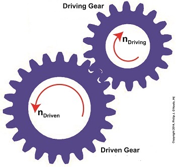
We’ve been working towards a general understanding of how gear trains work, and today we’ll solve a final piece of the puzzle when we identify how increased gear train torque is gained at the expense of gear train speed. Last time we developed a mathematical relationship between the torque, T, and the rotational speed, n, of the driving and driven gears in a simple gear train. This is represented by equation (8): TDriven ÷ TDriving = nDriving ÷ nDriven (8) For the purpose of our example we’ll assume that the driving gear is mounted to an electric motor shaft spinning at 100 revolutions per minute (RPM) and which produces 50 inch pounds of torque. Previous lab testing has determined that we require a torque of 100 inch pounds to properly run a piece of machinery that’s powered by the motor, and we’ve decided that the best way to get the required torque is not to employ a bigger, more powerful motor, but rather to install a gear train and manipulate its gear sizes until the desired torque is obtained. We know that using this approach will most likely affect the speed of our operation, and we want to determine how much speed will be compromised. So if the torque on the driven gear needs to be 100 inch pounds, then what will be the corresponding speed of the driven gear? To answer this question we’ll insert the numerical information we’ve been provided into equation (8). Doing so we arrive at the following: TDriven ÷ TDriving = nDriving ÷ nDriven (100 inch pounds) ÷ (50 inch pounds) = (100 RPM) ÷ nDriven 2 = (100 RPM) ÷ nDriven nDriven = (100 RPM) ÷ 2 = 50 RPM This tells us that in order to meet our torque requirement of 100 inch pounds, the gear train motor’s speed must be reduced from 100 RPM to 50 RPM, which represents a 50% reduction in speed, hence the tradeoff. This wraps up our blog series on gears and gear trains. Next time we’ll move on to a new topic: Galileo’s experiments with falling objects.
_______________________________________
|
Posts Tagged ‘driven gear’
Determining the Gear Train Tradeoff of Torque vs. Speed, Part Three
Wednesday, August 27th, 2014Determining the Gear Train Tradeoff of Torque vs. Speed, Part Two
Wednesday, August 20th, 2014|
In this blog series we’ve been examining gear train usefulness, specifically in terms of increasing torque. Equations presented last week began us on the final leg of our journey, and we’ve arrived at the point where the closing combination of equations will demonstrate the loss of speed that takes place when torque is increased within a gear train. To that end, the two main equations under consideration as presented last week, are:
where R is the gear ratio of the gear train, N is the number of gear teeth, n is the gear rotational speed in revolutions per minute (RPM), T is the torque, and D is the gear pitch radius. We were able to link these two equations by working through five key design equations applicable to simplified gear trains. For the full step-by-step progression see last week’s blog. After working through the equations presented last time we were able to arrive at an equation which links equations (1) and (2). Here it is:
If you follow the color coding, you’ll see the elements of equations (1) and (2) which come together in equation (7). Because equation (7) links the gear speed ratios (red) with the gear pitch radii ratios (green), we can set the ratios in equation (1) equal to those in equation (2). Doing so, we get: R = NDriven ÷ NDriving = nDriving ÷ nDriven = DDriven ÷ DDrivng = TDriven ÷ TDriving
In order to see the tradeoff between speed and torque, we need only consider the parts of the equation which concern themselves with factors relating to speed and torque. Removing the other unnecessary factors, we arrive at:
Next week we’ll plug numbers into equation (8) and disclose the tradeoff of speed for torque.
_______________________________________
|
Determining the Gear Train Tradeoff of Torque vs. Speed, Part One
Friday, August 15th, 2014|
Hold onto your hats, we’re going to deal with a lot of equations today! Last time we used flashbacks to previous blogs in this series to revisit key equations in our ongoing discussion of gear trains and torque. We also introduced The Law of Conservation of Energy in conjunction with five equations that together demonstrate how when increasing torque by use of a simple gear train, we do so at the cost of speed. Those five equations are:
where, R is the gear ratio, N the number of gear teeth, n the gear’s rotational speed, T the torque, D the gear pitch radius, and HP is the horsepower transmitted by the gears. As we work the equations, keep in mind that our ultimate objective is to find a way to link together (1) and (2), the equations dealing with gear torque and speed. Once we accomplish this we’ll see how increased torque is obtained at the cost of speed. But because there are no common terms between equations (1) and (2), our first step is to develop one. Developing a link between equations (1) and (2) is a process that begins with combining equations (2), (3), and (4).
The common terms in these three equations are TDriving and TDriven, so we’ll manipulate things in order to group them together. We’ll substitute equation (3) for the TDriving term in equation (2), and substitute equation (4) for the TDriven term in equation (2). We are now able to link all three equations to get: {[HPDriving ÷ nDriving] × 63,025} ÷ {[HPDriven ÷ nDriven] × 63,025} = DDriving ÷ DDriven (6) Now let’s go a step further to simplify equation (6). From equation (5) we know that the driving and driven gear horsepowers are equal. So, in equation (6), the HPDriving and HPDriven cancel out, along with the two 63,025 terms, allowing us to arrive at equation (7): {[HPDriving ÷ nDriving] × 63,025} ÷ {[HPDriven ÷ nDriven] × 63,025} = DDriving ÷ DDriven
Next week we’ll use equation (7) to link together R, N, n, of equation (1) with D and T of equation (2) and in so doing disclose mathematically the tradeoff between torque and speed, then apply our findings to an example. _______________________________________
|
The Gear Train Tradeoff
Tuesday, August 5th, 2014|
We’ve learned several methods to increase the torque of an electric motor through our series of articles on gear trains. One way is to attach a gear train to the motor’s shaft, a relatively simple thing to do. Today we’ll begin our exploration into how this method involves a tradeoff. It comes at the cost of speed. We’ll begin our examination of the tradeoff at play by linking together key elements learned through past blogs on the subject of gear trains. We’ll revisit those lessons through flashbacks. The first flashback we’ll make is to a blog entitled, Gear Ratio Formulas. There we learned that within a simple gear train consisting of two gears, the type most commonly employed to manipulate a motor’s torque, the ratio between the two gears, R, is relative to the ratio of their gear teeth, N. N is determined by the number of teeth each gear has in combination with the speeds, n, that each gear is going: R = NDriven ÷ NDriving = nDriving ÷ nDriven (1) The second flashback we’ll make is to a blog entitled, The Methodology Behind Gear Train Torque Conversions, in which we learned that the ratio of the torque, T, that exists between the gears is relative to the ratio of their respective pitch diameters, D: TDriving ÷ TDriven = DDriving ÷ DDriven (2) The tradeoff we’ve been alluding to comes in when gear speed, nDriven, represented in equation (1), is decreased, which results in an increase to TDriven in equation (2). But in order to see this we’ve got to somehow link the two equations together. In their present form there’s no common link between them. Or is there? There actually is an indirect link between the two equations, which comes by way of the torque equation presented in another past blog. The third flashback we’ll make is to the blog discussing that subject, which is entitled, The Relationship Between Torque and Horsepower. Using facts presented in that blog, the torque equations for our two gears become: TDriving = [HPDriving ÷ nDriving] × 63,025 (3) TDriven = [HPDriven ÷ nDriven] × 63,025 (4) Where’s the link between equations (1) and (2)? To answer that question we must reference a physics law known as The Law of Conservation of Energy . It states that the energy flowing from one gear to another within a gear train remains constant. Energy equates to horsepower, HP, in equations (3) and (4). So if the horsepower flowing through the gears is equal, our working equation becomes: HPDriving = HPDriven (5) Next time we’ll see how equation (5) is key to linking together equations (1) and (2) by way of equations (3) and (4). In so doing we’ll disclose the tradeoff to using gear trains. _______________________________________
|
How to Increase Gear Train Torque
Thursday, July 10th, 2014|
Last week we worked with a gear train equation and found that the gears under consideration were not sized properly to run a lathe. Today we’ll increase the gear train torque and solve that problem. How do we manipulate things to obtain the 275 inch pounds of torque required to drive the lathe? Last week we tried using a driven gear with a diameter of 8 inches and found that to be insufficient in size. So today the first thing we’ll try is a bigger driven gear, one with a pitch diameter of 8.5 inches. That’s 0.5 inches larger in diameter than the gear used in last week’s equation, and this just so happens to be the next size up in the gear manufacturer’s catalog. As we did last week, we’ll begin our calculations with the torque ratio equation: T1 ÷ T2 = D1 ÷ D2 We’ll use the same values as last week for T1, and D1, 200 inch pounds and 3 inches respectively, but we’ll increase the new value for D2, the driven gear pitch radius, to 4.25 inches (the new pitch diameter divided by two). Inserting these values into the torque equation, the only variable remaining without a value is torque T2. Let’s determine that value now by using algebra to rearrange terms. (200 inch pounds) ÷ T2 = (3 inches) ÷ (4.25 inches) (200 inch pounds) ÷ T2 = 0.70 T2 = (200 inch pounds) ÷ (0.70) = 283.33 inch pounds The value of T2 is found to be 283.33 inch pounds, which meets the torque requirement required to run the lathe. We were able to arrive at this torque by simply increasing the size of the driven gear relative to the size of the driving gear. In the world of Newtonian physics, this is a rather straightforward arrangement. It all boils down to this simple dynamic: When the motor’s force is acting upon a wider gear, the force is located a longer distance from the center of the driving gear shaft, which results in more torque on the shaft. As borne out by the example provided today, the larger the driven gear is in comparison to the driving gear, the more the gear train amplifies the torque that’s delivered by the motor. The principle at play here is exactly the same as that presented in a previous blog article where, for a given force exerted upon a wrench, torque was increased by simply increasing the length of the wrench handle. Some of you may be wondering why we didn’t just use a bigger, more powerful motor to begin with, thereby eliminating the need for a gear train and all the calculations we’ve been running? We’ll see why that’s not always possible or practical next time. _______________________________________
|
Determining Torque Within a Gear Train
Monday, June 30th, 2014|
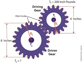
Last time we set up an example where an electric motor is connected to a lathe via a gear train. Today we’ll take the numerical values present on that gear train and plug them into the torque ratio equation we’ve been working with for the past few blogs. In the illustration below the electric motor exerts 200 inch pounds of torque upon the driving gear. The driving gear pitch circle diameter is 6 inches, while the driven gear pitch circle diameter is 8 inches. It’s been determined through previous lab testing that the lathe we’ll be using requires at least 275 inch pounds of torque to be exerted upon the driven gear shaft in order to operate properly. Will the gear train shown below meet this requirement? First, a review of the torque ratio equation: T1 ÷ T2 = D1 ÷ D2 Now we’ll crunch numbers. T1 is equal to 200 inch pounds, D1 is equal to 3 inches (pitch radius equals pitch diameter divided by two), and D2 is equal to 4 inches. This gives us: (200 inch pounds) ÷ T2 = (3 inches) ÷ (4 inches) T2 = (200 inch pounds) ÷ (0.75) = 266.67 inch pounds So, does the gear train as presented here supply enough torque to power the lathe properly? No, it does not. It provides only 266.67 inch pounds, not the 275 inch pounds of torque required. Next time we’ll see how to manipulate gear sizes within a gear train in order to meet a given torque requirement. _______________________________________
|
The Methodology Behind Gear Train Torque Conversions
Sunday, June 22nd, 2014|
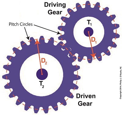
Last time we learned that gear trains are torque converters, and we developed a torque ratio equation which mathematically ties the two gears in a gear train together. That equation is: T1 ÷ T2 = D1 ÷ D2 Engineers typically use this equation knowing only the value for T2, the torque required to properly drive a piece of machinery. That knowledge is acquired through trial testing during the developmental phase of manufacturing. Once T2 is known, a stock motor is selected from a catalog with a torque value T1 which closely approximates that of the required torque, T2. Then calculations are performed and lab tests are run to determine the driving and driven gear sizes, D1 and D2 which will enable the gear train to convert T1 into the required value of T2. This series of operations are often a time consuming and complex process. To simplify things for the purpose of our example, we’ll say we’ve been provided with all values required for our equation, except one, the value of T2. In other words, we’ll be doing things in a somewhat reverse order, because our objective is simply to see how a gear train converts a known torque T1 into a higher torque T2. We’ll begin by considering the gear train illustration above. For our purposes it’s situated between an electric motor and the lathe it’s powering. The motor exerts a torque of 200 inch pounds upon the driving gear shaft of the lathe, a torque value that’s typical for a mid sized motor of about 5 horsepower. As-is, this motor is unable to properly drive the lathe, which is being used to cut steel bars. We know this because lab testing has shown that the lathe requires at least 275 inch pounds of torque in order to operate properly. Will the gears on our gear train be able to provide the required torque? We’ll find out next time when we insert values into our equation and run calculations. _______________________________________
|
Gear Train Torque Equations
Thursday, May 22nd, 2014|
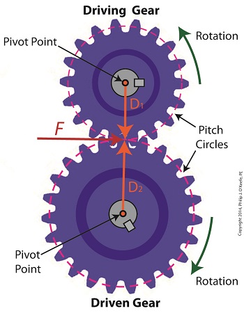
In our last blog we mathematically linked the driving and driven gear Force vectors to arrive at a single common vector F, known as the resultant Force vector. This simplification allows us to achieve common ground between F and the two Distance vectors of our driving and driven gears, represented as D1 and D2. We can then use this commonality to develop individual torque equations for both gears in the train. In this illustration we clearly see that the Force vector, F, is at a 90º angle to the two Distance vectors, D1 and D2. Let’s see why this angular relationship between them is crucial to the development of torque calculations. First a review of the basic torque formula, presented in a previous blog, Torque = Distance × Force × sin(ϴ) By inserting D1, F, and ϴ = 90º into this formula we arrive at the torque calculation, T1 , for the driving gear in our gear train: T1 = D1 × F × sin(90º) From a previous blog in this series we know that sin(90º) = 1, so it becomes, T1 = D1 × F By inserting D2, F, and ϴ = 90º into the torque formula, we arrive at the torque calculation, T2 , for the driven gear: T2 = D2 × F × sin(90º) T2 = D2 × F × 1 T2 = D2 × F Next week we’ll combine these two equations relative to F, the common link between them, and obtain a single equation equating the torques and pitch circle radii of the driving and driven gears in the gear train. _______________________________________ |
The Mathematical Link Between Gears in a Gear Train
Wednesday, May 14th, 2014|
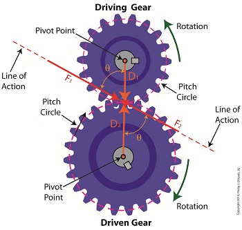
Last time we analyzed the angular relationship between the Force and Distance vectors in this simple gear train. Today we’ll discover a commonality between the two gears in this train which will later enable us to develop individual torque calculations for them. From the illustration it’s clear that the driving gear is mechanically linked to the driven gear by their teeth. Because they’re linked, force, and hence torque, is transmitted by way of the driving gear to the driven gear. Knowing this we can develop a mathematical equation to link the driving gear Force vector F1 to the driven gear Force vector F2, then use that linking equation to develop a separate torque formula for each of the gears in the train. We learned in the previous blog in this series that F1 and F2 travel in opposite directions to each other along the same line of action. As such, both of these Force vectors are situated in the same way so that they are each at an angle value ϴ with respect to their Distance vectors D1 and D2. This fact allows us to build an equation with like terms, and that in turn allows us to use trigonometry to link the two force vectors into a single equation: F = [F1 × sin(ϴ)] – [F2 × sin(ϴ)] where F is called a resultant Force vector, so named because it represents the force that results when the dead, or inert, weight that’s present in the resisting force F2 cancels out some of the positive force of F1. Next week we’ll simplify our gear train illustration and delve into more math in order to develop separate torque computations for each gear in the train. _______________________________________ |
Distance and Force Vectors of a Simple Gear Train
Monday, May 5th, 2014|
Last time we examined how torque and force are created upon the driving gear within a simple gear train. Today we’ll see how they affect the driven gear. Looking at the gear train illustration above, we see that each gear has both distance and force vectors. We’ll call the driving gear Distance vector, D1, and the driven gear Distance vector, D2. Each of these Distance vectors extend from pivot points located at the centers of their respective gear shafts. From there they extend in opposite directions until they meet at the line of action, the imaginary line which represents the geometric path along which Force vectors F1 and F2 are aligned. As we learned last time, the Force vector, F1, results from the torque that’s created at the pivot point located at the center of the driving gear. This driving gear is mounted on a shaft that’s attached to an electric motor, the ultimate powering source behind the torque. F1 follows a path along the line of action until it meets with the driven gear teeth, where it then exerts its pushing force upon them. It’s met by Force vector F2, a resisting force, which extends along the same line of action, but in a direction opposite to that of F1. These two Force vectors butt heads, pushing back against one another. F2 is essentially a negative force manifested by the dead weight of the mechanical load of the machinery components resting upon the shaft of the driving gear. Its unmoving inertia resists being put into motion. In order for the gears in the gear train to turn, F1 must be greater than F2, in other words, it must be great enough to overcome the resistance presented by F2. With the two Force vectors pushing against each other along the line of action, the angle ϴ between vectors F2 and D2, is the same as the angle ϴ between F1 and D1. Next time we’ll use the angular relationship between these four vectors to develop torque calculations for both gears in the gear train. _______________________________________ |
