Posts Tagged ‘power supply’
Transistors – Voltage Regulation Part XVII
Monday, November 12th, 2012
Transistors – Voltage Regulation Part XVI
Monday, November 5th, 2012
Transistors – Voltage Regulation Part XIV
Monday, October 22nd, 2012|
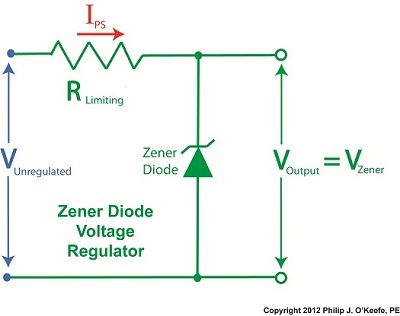
As we’ve come to know through this series of blogs, all electronic components pose some degree of internal resistance to the electric current flowing through them. This resistance results in electrical energy being converted into heat energy, heat which poses potential problems to sensitive components like electronic circuit boards. If things get hot enough, components fail and fires may ignite. To address these issues engineers design circuits with resistors whose job it is to limit the current flowing to electrical components. In this article we’ll see how a limiting resistor protects a Zener diode from this fate, allowing it to continue doing its job of regulating voltage. In our last blog we applied Ohm’s Law to our regulated power supply circuit, which makes use of a Zener diode. See Figure 1. Figure 1
Ohm’s Law gave us the following equation to determine the amount of current, IPS, flowing from the unregulated power supply portion, through the current limiting resistor RLimiting, and making its way into the rest of the circuit: IPS = (VUnregulated – VZener) ÷ RLimiting We learned last week that for the circuit to work, the voltage of the unregulated power supply portion of the circuit, VUnregulated, must be greater than the Zener voltage, VZener. Looking at the equation above, we see that the voltage difference is divided by RLimiting, the value of the limiting resistor in the circuit. This limiting resistor is there to constrain the current flowing to the Zener diode, allowing the diode to keep things under control within the circuit. Basic mathematical principles hold that if a smaller number is divided by a bigger number, the resulting answer is an even smaller number. Applying this principle to the equation above, if RLimiting is a big number, then IPS must be a smaller number. On the other hand the smaller RLimiting gets, the bigger IPS becomes. So what does it take for our circuit to fail? Remove the limiting resistor as shown in Figure 2 and the value for RLimiting disappears. In other words, RLimiting becomes zero.
Figure 2
In this case our Ohm’s Law equation becomes: IPS = (VUnregulated – VZener) ÷ 0 = ∞ The resulting answer is said to go to infinity, or ∞, as it is represented mathematically. In other words, without a limiting resistor being employed within our circuit, IPS will become so large it will overwhelm the diode’s current handling capacity and lead to circuit failure. Next time we’ll go over some advantages and disadvantages of this Zener diode voltage regulating circuit, and why the disadvantages outweigh the advantages for many applications. ____________________________________________ |


Transistors – Voltage Regulation Part VIII
Sunday, September 9th, 2012| Back in the early 1970s my dad, a notorious tightwad, coughed up several hundred dollars to buy his first portable color television. That was a small fortune back then. The TV was massive, standing at 24 inches wide, 18 inches high, and 24 inches deep, and weighing in at about 50 pounds. I think the only thing that made this behemoth “portable” was the fact that it had a carrying handle on top.
A major reason for our old TV being so big and clunky was of course due to limitations in technology of the time. Many large, heavy, and expensive electronic components were needed to make it work, requiring a lot of space for the circuitry. By comparison, modern flat screen televisions and other electronic devices are small and compact because advances in technology enable them to work with far fewer electronic components. These components are also smaller, lighter, and cheaper. Last time we looked at the components of a simple unregulated power supply to see how it converts 120 volts alternating current (VAC) to 12 volts direct current (VDC). We discovered that the output voltage of the supply is totally dependent on the design of the transformer, because the transformer in our example can only produce one voltage, 12 VDC. This of course limits the supply’s usefulness in that it is unable to power multiple electronic devices requiring two or more voltages, such as we’ll be discussing a bit further down. Now let’s illustrate this power supply limitation by revisiting our microprocessor control circuit example which we introduced in a previous article in this series on transistors.
Figure 1
In Figure 1 we have to decide what kind of power to supply to the circuit, but we have a problem. Sure, the unregulated power supply that we just discussed is up to the task of providing the 12 VDC needed to supply power for the buzzer, light, and electric relay. But let’s not forget about powering the microprocessor chip. It needs only 5 VDC to operate and will get damaged and malfunction on the higher 12 VDC the current power supply provides. Our power supply just isn’t equipped to provide the two voltages required by the circuit. We could try and get around this problem by adding a second unregulated power supply with a transformer designed to convert 120 VAC to 5 VAC. But, reminiscent of the circuitry in my dad’s clunky old portable color TV, the second power supply would require substantially more space in order to accommodate an additional transformer, diode bridge, and capacitor. Another thing to consider is that transformers aren’t cheap, and they tend to have some heft to them due to their iron cores, so more cost and weight would be added to the circuit as well. For these reasons the use of a second power supply is a poor option. Next time we’ll look at how adding a transistor voltage regulator circuit to the supply results in cost, size, and weight savings. It also results in a more flexible and dependable output voltage. ____________________________________________ |

Transistors – Voltage Regulation Part VI
Sunday, August 26th, 2012| Believe it or not as a kid in grade school I used to hate math, particularly algebra. None of my teachers were able to decipher its complexities and render it comprehensible to me or the majority of my classmates. Then in high school everything changed. I had Mr. Coleman for freshman algebra, and he had a way of making it both understandable and fun, in a challenging kind of way. With 40 years of teaching under his belt, Mr. Coleman knew exactly how to convey the required information in an understandable manner, and to this day I find his insights useful in solving engineering calculations.
Last time we began our discussion on Ohm’s Law and how it may be applied to our example circuit to solve for the electrical current flowing through it. Let’s continue our discussion to see how the Law applies to only one part of the circuit. Then, we’ll use a little algebra to show how the output voltage of an unregulated power supply is affected by changes in RTotal.
Figure 1
To help us see things more clearly, in Figure 1 we’ll cover up the inside workings of the unregulated power supply side of the circuit and concentrate on the external supply part of the circuit alone. Since RTotal is connected to the terminals of the power supply, the voltage applied to RTotal is the same as the power supply output voltage, VOutput. In my previous article, we learned that according to Ohm’s Law, the current flowing through a resistance is equal to the voltage applied to it, divided by the resistance. The fact that RTotal is connected to the two output terminals like we see in Figure 1, allows us to use Ohm’s law to solve for the electrical current, I, flowing through RTotal: I = VOutput ÷ RTotal Now let’s pull the cover off of the unregulated power supply again to see what’s going on within the circuit as a whole.
Figure 2
In Figure 2 we can see that the current, I, flowing through RTotal is the same current flowing through the balance of the circuit. In the preceding blog we found that value to be: I = VDC ÷ (RInternal + RTotal) We can combine the above two equations for I to develop an algebraic relationship between VOutput and RInternal, RTotal, and VDC: VOutput ÷ RTotal = VDC ÷ (RInternal + RTotal) Then, by rearranging terms and applying the cross multiplication principle of algebra we can solve for VOutput. This involves multiplying both sides of the equation by RTotal: VOutput = RTotal × (VDC ÷ (RInternal +RTotal)) This equation tells us that although RInternal doesn’t fluctuate, VOutput will fluctuate when RTotal does. This fact is demonstrated in our equation when we make use of algebra. That is to say, when a term changes on one side of the equation, it causes the other side of the equation to change as well. In this case, when RTotal changes, it causes VOutput to change in proportion to the fixed values of VDC and RInternal. Next time we’ll look at another shortcoming of unregulated power supplies, more specifically, how one supply can’t power multiple electrical circuits comprised of different voltages. ____________________________________________ |


Transistors – Voltage Regulation Part III
Tuesday, August 7th, 2012| When my daughter was seven she found out about Ohm’s Law the hard way, although she didn’t know it. She had accidentally bumped into her electric toy train, causing its metal wheels to derail and fall askew of the metal track. This created a short circuit, causing current to flow in an undesirable direction, that is, through the derailed wheels rather than along the track to the electric motor in the locomotive as it should.
What happened during the short circuit is that the bulk of the current began to follow through the path of least resistance, that of the derailed wheels, rather than the higher resistance of the electric motor. Electric current, always opportunistic, will flow along its easiest course, in this case the short, thick metal of the wheels, rather than work its way along the many feet of thin metal wire of the motor’s electromagnetic coils. With its wheels sparking at the site of derailment the train had become an electric toaster within seconds, and the carpet beneath the track began to burn. Needless to say, mom wasn’t very happy. In this instance Ohm’s Law was at work, with a decidedly negative outcome. The Law’s basic formula concerning the toy train would be written as: I = V ÷ Rwhere, I is the current flowing through the metal track, V is the track voltage, and R is the internal resistance of the metal track and locomotive motor, or in the case of a derailment, the metal track and the derailed wheel. So, according to the formula, for a given voltage V, when the R got really small due to the derailment, I got really big. But enough about toy trains. Let’s see how Ohm’s Law applies to an unregulated power supply circuit. We’ll start with a schematic of the power supply in isolation.
Figure 1The unregulated power supply shown in Figure 1 has two basic aspects to its operation, contained within a blue dashed line. The dashed line is for the sake of clarity when we connect the power supply up to an external circuit which powers peripheral devices later on. The first aspect of the power supply is a direct current (DC) voltage source, which we’ll call VDC. It’s represented by a series of parallel lines of alternating lengths, a common representation within electrical engineering. And like all electrical components, the power supply has an internal resistance, such as discussed previously. This resistance, notated RInternal, is the second aspect of the power supply, represented by another standard symbol, that of a zigzag line. Finally, the unregulated power supply has two output terminals. These will connect to an external supply circuit through which power will be provided to peripheral devices. Next time we’ll connect to this external circuit, which for our purposes will consist of an electric relay, buzzer, and light to see how it all works in accordance with Ohm’s Law. ____________________________________________ |

Transistors – Voltage Regulation Part II
Sunday, July 29th, 2012| I joined the Boy Scouts of America as a high schooler, mainly so I could participate in their Explorer Scout program and learn about electronics. I will forever be grateful to the Western Electric engineers who volunteered their personal time to stay after work and help me and my fellow Scouts build electronic projects. The neatest part of the whole experience was when I built my first regulated power supply with their assistance inside their lab. But in order to appreciate the beauty of a regulated power supply we must first understand the shortcomings of an unregulated one, which we’ll begin to do here.
Last time we began to discuss how the output voltage of an unregulated power supply can vary in response to power demand, just as when sprinklers don’t have sufficient water flow to cover a section of lawn. Let’s explore this concept further.
Figure 1
Figure 1 shows a very basic representation of a microprocessor control system that operates three components, an electric relay (shown in the blue box), buzzer, and light. These three components have a certain degree of internal electrical resistance, annotated as RR, RB, and RL respectively. This is because they are made of materials with inherent imperfections which tend to resist the flow of electric current. Imperfections such as these are unavoidable in any electronic device made by humans, due to impurities within metals and irregularities in molecular structure. When the three components are activated by the microprocessor chip via field effect transistors, denoted as FET 1, 2 and 3 in the diagram, their resistances are connected to the supply circuit. In other words, RR, RB, and RL create a combined level of resistance in the supply circuit by their connectivity to it. If a single component were to be removed from the circuit, its internal resistance would also be removed, resulting in a commensurate decrease in total resistance. The greater the total resistance, the more restriction there is to current flow, denoted as I. The greater the resistance, the more I is caused to decrease. In contrast, if there is less total resistance, I increases. The result of changing current flow resistance is that it causes the unregulated power supply output voltage to change. This is all due to an interesting phenomenon known as Ohm’s Law, represented as this within engineering circles: V = I × R where, V is the voltage supplied to a circuit, I is the electrical current flowing through the circuit, and R is the total electrical resistance of the circuit. So, according to Ohm’s Law, when I and R change, then V changes. Next time we’ll apply Ohm’s Law to a simplified unregulated power supply circuit schematic. In so doing we’ll discover the mathematical explanation to the change in current flow and accompanying change in power supply output voltage we’ve been discussing. ____________________________________________ |

Transistors – Voltage Regulation
Sunday, July 22nd, 2012| Electrical voltage flow and water flow have a lot in common. They’re both affected by fluctuations in supply, fluctuations which can adversely impact both performance and equipment integrity. Take for example a sprinkler that fails to cover a designated section of lawn due to heavy neighborhood demand. Everybody wants to water on the weekend when it’s been 90 degrees all week, and low water pressure is the result. There are times when it’s hard to get a glass of water. By contrast in the winter months, when water demands tend to be lower, water supplies are plentiful. This scenario of varying water pressure is analogous to what sometimes occurs within electric circuits.
In my previous blog article on wall warts, I described the operation of a simple power supply consisting of a transformer, diode bridge, and capacitor. Together, these components converted 120 volts alternating current (VAC) to 12 volts direct current (VDC). The wall wart power supply is fine for many applications, however it is unregulated, meaning if there are any sudden surges in power, such as spikes or dips caused by lightning strikes or other disturbances on the electric utility system, there could be problems.
Take for example a power supply that is used in conjunction with sensitive digital logic chips, like the one used in my x-ray film processor design shown in my last blog article. These chips are designed to run optimally on a constant voltage, like 5 VDC, and when that doesn’t happen input signals can fail to register with the computer program and cause a variety of problems, such as output signals turning on and off at will. In the film processor the drive motor may start at the wrong time or get stuck in an on modality. If power surges are high enough, microprocessor chips can get damaged, compromising the entire working unit. The output voltage of an unregulated power supply can also vary in response to power demand, just as when sprinklers don’t have sufficient water flow to cover a section of lawn. Demand for power can change within a circuit when electrical components like relays, lights, and buzzers are turned on and off by digital logic chips. Next time we’ll take a look at a basic concept of electrical engineering known as “Ohm’s Law” and how it governs the variable output voltage response of unregulated power supplies.
____________________________________________ |
Transistors – Digital Control Interface, Part V
Sunday, July 15th, 2012| Last time we looked at my electric relay solution to a problem presented by a 120 volt alternating current (VAC) drive motor operating within an x-ray film processing machine. Now let’s see what happens when we press the button to set the microprocessor into operation.
Figure 1Figure 1 shows that when the button is depressed, the computer program contained within the microprocessor chip goes into action, signaling the start of the control initiative. 5 volts direct current (VDC) is supplied to Output Lead 2, and FET 2 (Field Effect Transistor 2) becomes activated, which allows electric current from the 12 VDC supply to course into the 12 VDC electric relay, through the relay’s wire coil, then conclude its travel into electrical ground. The electric relay components, including a wire coil, steel armature, spring, and normally open (N.O.) contact, are shown within a blue box in our illustration. Current flow is represented by red lines. The control initiative passes from the microprocessor to FET 2, and then to the 12 VDC electric relay, just as the Olympic Torch is relayed through a system of runners. We learned in one of my previous articles on industrial control that when an electric relay coil is energized, electromagnetic attraction pulls its steel armature towards the wire coil and the N.O. electrical contact. In Figure 1 this attraction is represented by a blue arrow. With the N.O. contact closed the drive motor is connected to the 120 VAC input, and the motor is activated.
Figure 2
Figure 2 shows what happens after the button is depressed. The computer program is activated, directing the microprocessor chip to keep 5 VDC on Output Lead 2 and FET 2 while the prerequisite 40 minutes elapses. Thus the relay remains energized and the motor remains on during this time.
Figure 3
In Figure 3, at the end of the 40 minute countdown, the computer program applies 0 VDC to Output Lead 2. FET 2 then turns off the current flow to the relay and it begins to de-energize, causing the spring to pull the steel armature away from the N.O. contact and the 120 VAC power supply to be interrupted. The motor is deactivated. At the same time, the computer program applies 5 VDC to Output Lead 1 and FET 1 for 2 seconds. FET 1 turns on the flow of current through the buzzer, causing it to sound off and signal that the x-ray film processing machine is ready for use. Next time we’ll look at how transistors are used to regulate voltage within direct current power supplies like the one shown in Figure 3 above. ____________________________________________ |


Transistors – Digital Control Interface, Part III
Sunday, July 1st, 2012| When I was in engineering school in the mid 1970s microprocessor chips were still a fairly new concept. Scientific calculators were the size of a brick back then, and they weighed almost as much, and there were no personal computers.
I remember doing homework on the UNIVAC 1108 mainframe computer at school. To program it I had to sit at a monster of a keypunching machine for which I punched an endless array of holes into paper cards. These holes acted as the programming logic to instruct the computer what functions to perform. The 1108 computer’s mainframe was so huge it was housed in an adjoining room the size of a house. Since the 1980s advances in microprocessor technology have increased computing power and dramatically reduced the size of components, making things like laptops, smart phones, and sophisticated electronic products possible. Last time we began looking at my design solution for the control of a machine which developed medical x-ray film and made use of a microprocessor chip to automate its operation. A field effect transistor (FET) acts as a digital control interface between its 5 volt direct current (VDC) microprocessor and a 12 VDC buzzer. Figure 1 shows what happens when someone presses the button to put everything into action and the microprocessor starts timing. Figure 1
With the button depressed the chip senses 5 VDC from the power supply on its input lead. This in turn signals the computer program to turn the product on. The program then begins counting down the minutes, all the while maintaining a 0 voltage output from the chip’s output lead. With no voltage present on its G lead, the FET does not permit electrical current to flow from the 12 VDC supply, through the buzzer, through D and S, and down to electrical ground. The buzzer remains silent.
Figure 2Figure 2 shows what happens when the program begins its 40-minute warming sequence. The chip raises the output lead voltage to 5 VDC and applies it to G, then the FET permits electric current to flow through it to ground from the 12 VDC supply and the buzzer. Now supplied with power, the buzzer sounds. Then, per programming instructions, after 2 seconds the program shuts off the voltage in the chip’s output lead, current is cut off, and the buzzer goes silent. Next time we’ll see how an FET can be used as an interface between a microprocessor and another higher powered device, that of a 120 VAC motor that’s used to move x-ray film through a series of processes within the developer.
____________________________________________ |


